Wireless power supply device and method applied to electronic lock

a technology of wireless power supply and electronic lock, which is applied in the direction of individual entry/exit registers, instruments, transportation and packaging, etc., can solve the problems of unsafe to directly power on the electronic lock to unlock, no signal encryption design between the power supply unit and the power receiving unit, etc., and achieve the effect of greatly improving security

Pending Publication Date: 2022-08-11
POWERTEK HARDWARE CO LTD
View PDF0 Cites 0 Cited by
  • Summary
  • Abstract
  • Description
  • Claims
  • Application Information

AI Technical Summary

Benefits of technology

[0008]In the wireless power supply device and method applied to an electronic lock provided by the present invention, the power supply unit and the power receiving unit will first confirm whether they are paired objects, if so, the power is allowed to be tr

Problems solved by technology

However, there is no signal encryption design between the power supply unit and the power receiving unit, and the

Method used


Image

  • Wireless power supply device and method applied to electronic lock
  • Wireless power supply device and method applied to electronic lock
  • Wireless power supply device and method applied to electronic lock

Examples


Embodiment Construction

[0013]Embodiments of the present invention will now be described, by way of example only, with reference to the accompanying drawings.

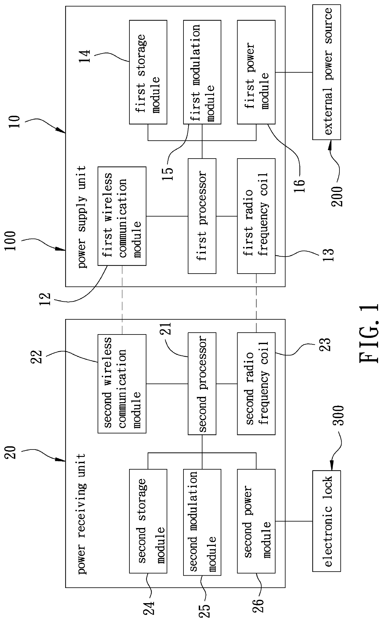
[0014]FIG. 1 is a block diagram of a preferred embodiment of the present invention. The present invention discloses a wireless power supply device 100, comprising a power supply unit 10 and a power receiving unit 20.

[0015]The power supply unit 10 has a first processor 11. The first processor 11 is electrically connected to a first wireless communication module 12, a first radio frequency coil 13, a first storage module 14, a first modulation module 15 and a first power module 16. The first wireless communication module 12 is an infrared transmitter. The first power module 16 is electrically connected to an external power source 200 for receiving power provided by the external power source 200.

[0016]The power receiving unit 20 is arranged face-to-face with the power supply unit 10 and keeps a distance from the power supply unit 10. The power receiving ...


PUM


Abstract

A wireless power supply device and method applied to an electronic lock is implemented between a power supply unit and a power receiving unit. The power supply unit is connected to an external power source and has a first radio frequency coil and a first wireless communication module. The power receiving unit is connected to an electronic lock and has a second radio frequency coil and a second wireless communication module. When the power supply unit wirelessly transmits the power provided by the external power source to the power receiving unit, the power receiving unit and the power supply unit perform a handshaking process to confirm whether they are paired objects, if yes, the power is allowed to be transmitted to the electronic lock, so that the security of wireless power supply can be improved.

Description

FIELD OF THE INVENTION[0001]The present invention relates to a wireless power supply technology, and more particularly to a wireless power supply device and method applied to an electronic lock.BACKGROUND OF THE INVENTION[0002]A conventional wireless power supply device has a power supply unit and a power receiving unit. The power supply unit is mounted to the door frame of a door body, and is connected with an external power source. The power receiving unit is mounted to the door panel of the door body and is connected with an electronic lock. The power supply unit and the power receiving unit are a coil winding structure, which can wirelessly transmit the power provided by the external power source to the electronic lock through electromagnetic induction.[0003]However, there is no signal encryption design between the power supply unit and the power receiving unit, and there is no relevant verification mechanism. In general, the above-mentioned electronic lock is unlocked by energi...

Claims


Application Information

Patent Timeline
IPC IPC(8): H02J50/10G07C9/00H02J50/80H02J7/00H04B5/00G06K19/04
CPCH02J50/10G07C9/00309H02J50/80H02J7/0042G07C2009/00634H04B5/0037H04B5/0031G06K19/045H04B5/0093E05B2047/0061
Inventor CHEN, CHUNG-YU
Owner POWERTEK HARDWARE CO LTD
Why Eureka
Try Eureka