

Transformer Sub-Pistol Firearm
a transformer and sub-pistol technology, applied in the field of firearms, can solve problems such as wasting essential tim
- Summary
- Abstract
- Description
- Claims
- Application Information
AI Technical Summary
Problems solved by technology
Method used
Image

Examples
Embodiment Construction
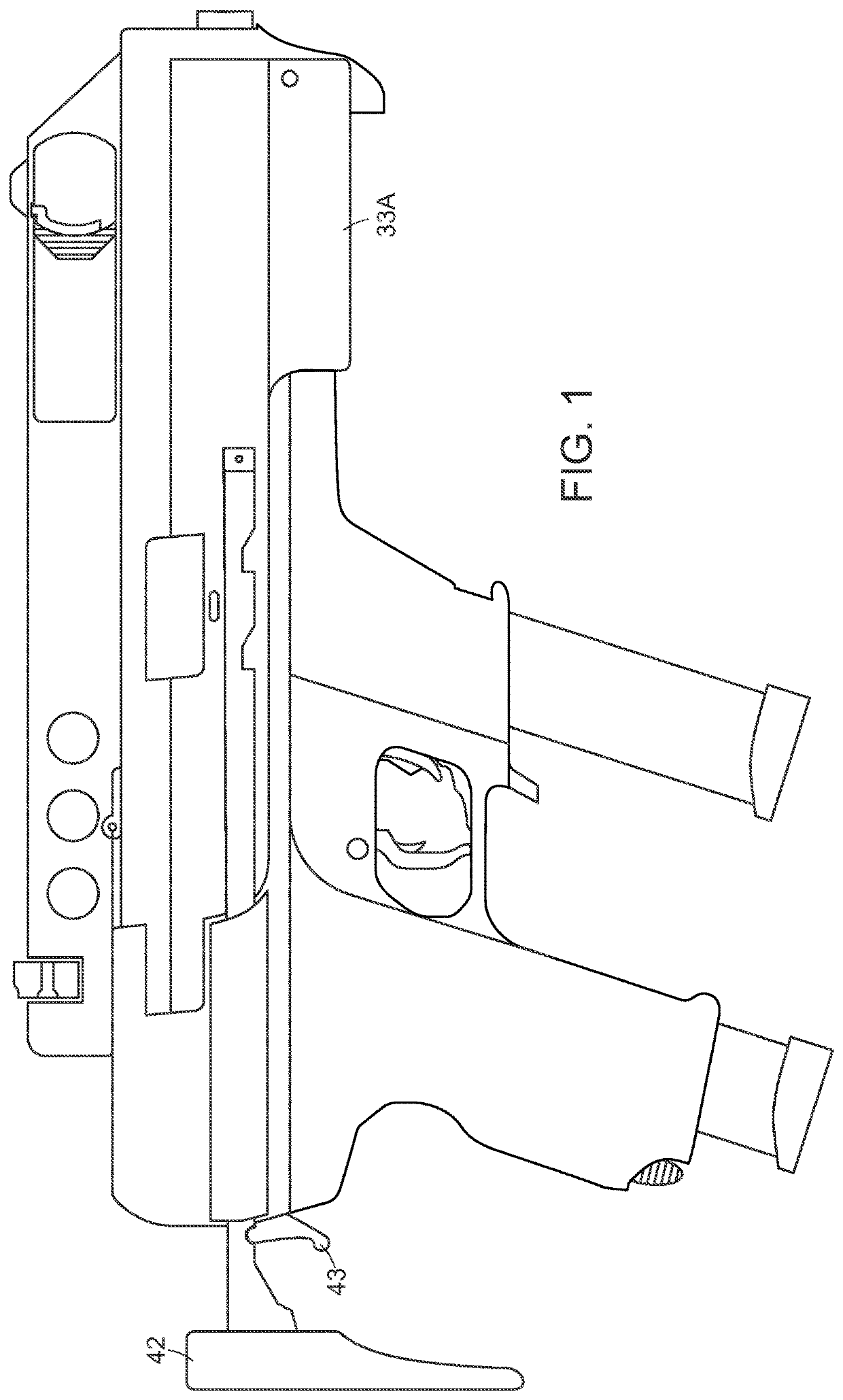
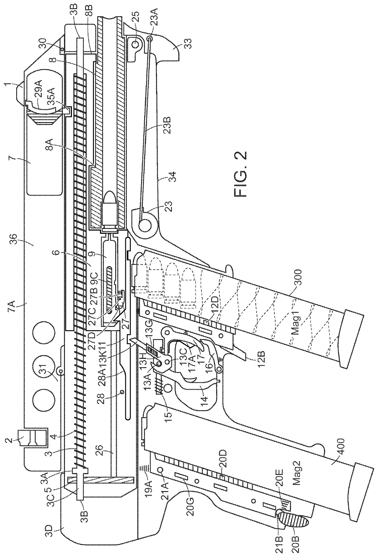
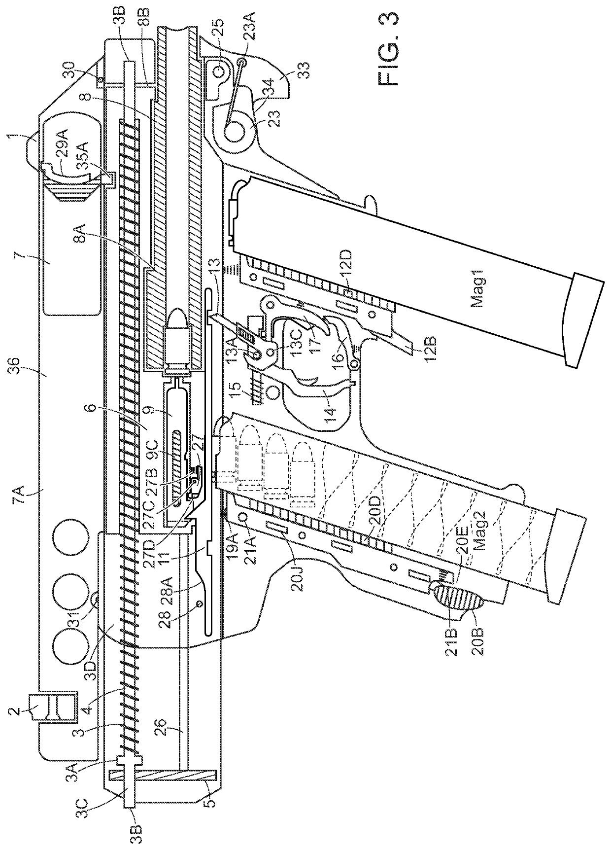
[0044]The presently disclosed firearm advantageously makes use of the both sub-machine gun and pistol firing configurations to provide a carbine firearm that transforms from a submachine gun firing mode to a pistol firing mode, and is able to fire a projectile from a first magazine in a submachine gun configuration and is also able to fire a projectile from second magazine in a pistol configuration. The disclosed firearm is thus referred to herein as a “transformer sub-pistol.” In some embodiments, the barrel of the disclosed transformer sub-pistol has a maximum length of 5.5 inches. In some embodiments, the total weapon length is a maximum of 13 inches. This compact size is advantageous for use in close combat.
[0045]The presently disclosed firearm makes use of many features standard to semi-automatic pistols and submachine guns, and thus, prior to discussing the mechanics of the transformer sub-pistol, a brief discussion of the manner in which a semiautomatic weapon is fired is fir...
PUM
 Abstract
Description
Claims
Application Information