System and method for monitoring the stability of a scintillation detector

a scintillation detector and stability monitoring technology, applied in the direction of calibration apparatus, nuclear radiation detection, geological measurements, etc., can solve the problem that the use of calibration may change significantly

Inactive Publication Date: 2000-05-16
INST OF GEOLOGICAL & NUCLEAR SCI
View PDF1 Cites 31 Cited by
  • Summary
  • Abstract
  • Description
  • Claims
  • Application Information

AI Technical Summary

Benefits of technology

The present invention provides a system and method for monitoring the stability of a scintillation detector which can be arranged to sense gain changes in the scintillation detector simultaneously as a measuring system is operating without interruption of the measuring process.

Problems solved by technology

A particular problem with scintillation detectors using photomultipliers is that they are prone to gain drift which means that in continuous use the calibration may change significantly.
This may require periodically stopping the industrial measurement and moving the detector to a re-calibration location which is a problem requirement.

Method used


Image

  • System and method for monitoring the stability of a scintillation detector
  • System and method for monitoring the stability of a scintillation detector

Examples


Embodiment Construction

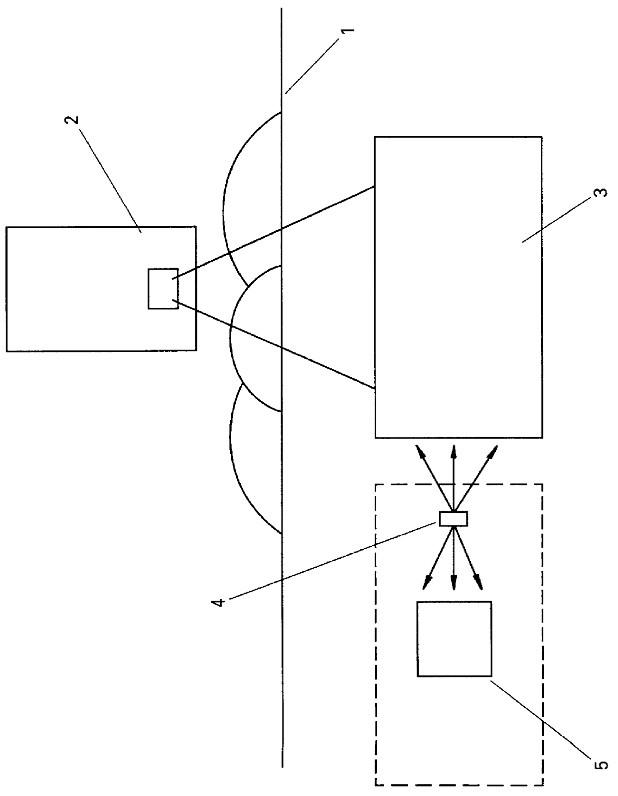
FIG. 1 schematically illustrates an industrial measuring apparatus in which items to be scanned are passed by means of a conveyor 1 between a primary radiation source 2 and a primary scintillation cell or detector 3. The primary source may be a Cf-252 neutron-gamma source for example.

A low level subsidiary gamma source 4 with suitable collimation provides one stream of gamma radiation which is aimed into the primary scintillation cell 3 and another stream which is used as a reference and is aimed into a reference counter 5. The subsidiary source may be a Na-22 source or a Co-60 source for example. In the preferred form system the primary source provides fast neutron and gamma radiation with which the items under test are irradiated, both neutron and gamma radiation are detected, and the extent to which each species of the source radiation is transmitted through the item is measured by the detector 3 and analysed.

The subsidiary source 4 provides two gammas beams at 511 keV simultaneo...


PUM


Abstract

A system for on-line monitoring the stability of a scintillation detector, comprises means providing two beams of gamma rays from a subsidiary source which are distinguishable because of their time relationship from the primary source. The two beams are of similar energies but are oriented in different directions, with one directed into the scintillation detector and one acting as a reference beam and directed to a reference beam counter. The ratio of the detector-count rate for the timed events to the reference count rate is compared to provide an indication of any drift in the scintillation detector.

Description

The invention comprises a system and method for monitoring the stability of a scintillation detector, typically in an industrial application.Traditionally, scintillation detectors have been used in research applications in laboratories but they are more recently finding important applications in industry. A particular problem with scintillation detectors using photomultipliers is that they are prone to gain drift which means that in continuous use the calibration may change significantly. This may require periodically stopping the industrial measurement and moving the detector to a re-calibration location which is a problem requirement. The scintillation detectors typically used to implement the measuring system described in New Zealand patent 213777 / 214666 also employ pulse shape discrimination to separate neutron and gamma events which is a temperature dependent process. A procedure adopted to minimise gain stabilisation problems is to control the temperature of the detector, but ...

Claims


Application Information

Patent Timeline
Patent Type & Authority Patents(United States)
IPC IPC(8): G01T1/202G01T1/00G01T1/40
CPCG01T1/40G01T1/202
Inventor BARTLE, COLIN M
Owner INST OF GEOLOGICAL & NUCLEAR SCI
Why Eureka
Try Eureka