Random character selector device

a random character selector and selector technology, applied in the field of random character selector devices, can solve the problems of no above-mentioned device providing a simple, manually-activated random character selector

Inactive Publication Date: 2000-08-22
FURLONG ROBIN
View PDF25 Cites 8 Cited by
  • Summary
  • Abstract
  • Description
  • Claims
  • Application Information

AI Technical Summary

Benefits of technology

By another feature of this invention and of the above feature, the stop members comprise four vertically-extended teeth on the spinnable cylinder, and the stopping means comprises a pawl which is springingly mounted or a mounting plate which is secured to the circular rear face.
By other features of this invention and of the

Problems solved by technology

None of the above devices provided a simple, manually-activated, random ch

Method used


Image

  • Random character selector device
  • Random character selector device
  • Random character selector device

Examples


Embodiment Construction

(a) Description of FIG. 1

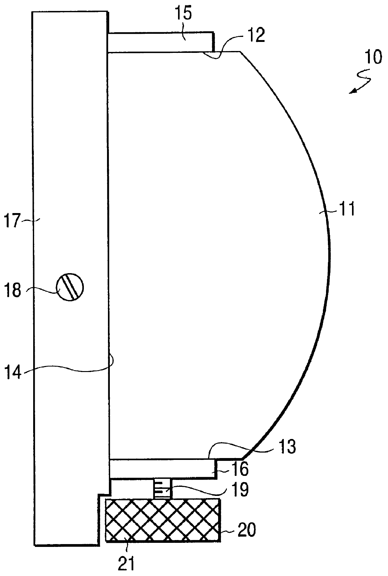
As seen in FIG. 1, the random character selector is a housing 10 which preferably takes the form of a globular member, e.g., a billiard ball 11, in which a portion of the top has been sliced off to form a circular, top face 12, in which a portion of the bottom has been sliced off to form a bottom face 13, and in which a portion of the rear has been sliced off to form a rear circular face 14. The top face 12 is fitted with a view cover 15, the bottom face 13 is fitted with a bearing sheath 16, and the rear face 14 is fitted with a back plate 17, which is secured to the globular member 11 by means of two screws, one of which 18 being shown.

Projecting below bearing sheath 16 is a central longitudinal shaft 19 of a spinnable cylinder, to be described in greater detail with respect to FIG. 2. A spinning dial 20 having a knurled gripping surface 21 is threadedly secured to the shaft 19, although other equivalent securing means may be used.

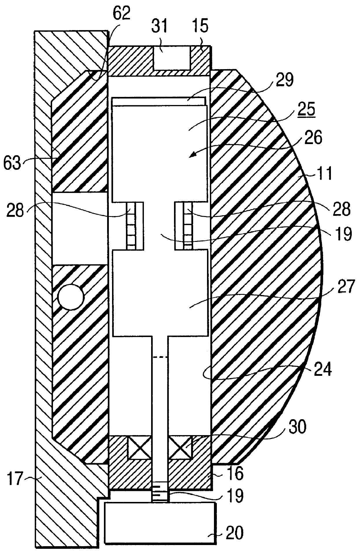
(b) Description of FIG. 2...


PUM


Abstract

A random selector is provided herein. It includes a housing, e.g., a cylindrical housing in which a portion of the rear curved portion is sliced away to provide a generally-rectangular rear face, or a housing in the form of a globular member in which a portion of an upper end has been sliced away to provide an upper circular face, a portion of a lower end has been sliced away to provide a lower circular face, and in which a portion of the rear race has been sliced off to provide a circular rear face. A spinnable member, e.g., in the form of a spinnable cylinder, is rotatably mounted within the housing and is spinnable about a vertical area of the housing. A plurality of character indicia, e.g., "H" (heads), "T" (tails), is provided in an upper face, e.g., the upper circular face of the spinnable cylinder. A window is provided in the housing. An activation mechanism is operatively associated with the spinnable cylinder. An operator device is operatively associated with the activation mechanism to spin the wheel in a free-wheeling manner. A stopping device is provided for stopping the spinnable cylinder by a friction stop mechanism, e.g., by teeth on the spinnable cylinder. The stopping device includes spring clips which are biassed to the "at rest" position but which are operated automatically alternately to engage and to disengage the teeth to stop the spinner. This then displays one randomly-selected character, e.g. "H" or "T" through the window.

Description

(a) Field of the InventionThis invention relates to a random character selector device. In particular, it relates to a heads-tail coin selection device as a pseudo coin toss device.(b) Description of the Prior ArtU.S. Pat. No. 1,986,838, patented Jan. 8, 1935, by George D. Manville, provided a random selection device in the form of a machine including a spinnable wheel provided with a full deck of playing cards including the "joker." It included means whereby the wheel could be spun and then be manually stopped at will in an endeavour to register a desired card of the deck at a give index position. The machine included a wheel which rotated freely when activated by a hand crank, which was connected to a spinning mechanism. An automatic brake device was controlled by the crank released the carrier for spinning action and permitted the brake to act, at the player's will, to stop the wheel. A centering device registered a halted card with the index. Means, controlled by the crank, rele...

Claims


Application Information

Patent Timeline
IPC IPC(8): A63F9/04G07C15/00
CPCA63F9/0406G07C15/003A63F2009/0417
Inventor FURLONG, ROBIN
Owner FURLONG ROBIN
Why Eureka
Try Eureka