Color picture tube device having contoured panel and auxiliary coil for reducing apparent screen distortions

a tube device and contoured technology, applied in the direction of cathode ray tubes/electron beam tubes, electrical discharge tubes, electrical equipment, etc., can solve the problems of anisotropy of apparent screen, flat panel has not been used for weight reduction, and flatness in the vertical direction still produces uncomfortable impressions

Inactive Publication Date: 2000-10-17
THOMSON LICENSING SA
View PDF14 Cites 10 Cited by
  • Summary
  • Abstract
  • Description
  • Claims
  • Application Information

AI Technical Summary

Problems solved by technology

Since conventionally used color picture tubes are made of vacuum chambers of glass, flat panels have not been used for weight reduction.
However, the insufficient flatness in the horizontal direction and the problem of flatness in the vertical direction still produce an uncomfortable impression.
Conventionally, since it was impossible to adjust the apparent rise of the screen in the vertical direction, the apparent screen had anisotropy leading to inferior flatness.
Furthermore, conventional color picture tube panels had problems in static strength of the picture tubes to some extent, since they had no wedge.

Method used


Image

  • Color picture tube device having contoured panel and auxiliary coil for reducing apparent screen distortions
  • Color picture tube device having contoured panel and auxiliary coil for reducing apparent screen distortions
  • Color picture tube device having contoured panel and auxiliary coil for reducing apparent screen distortions

Examples


Embodiment Construction

A-1. Device Structure

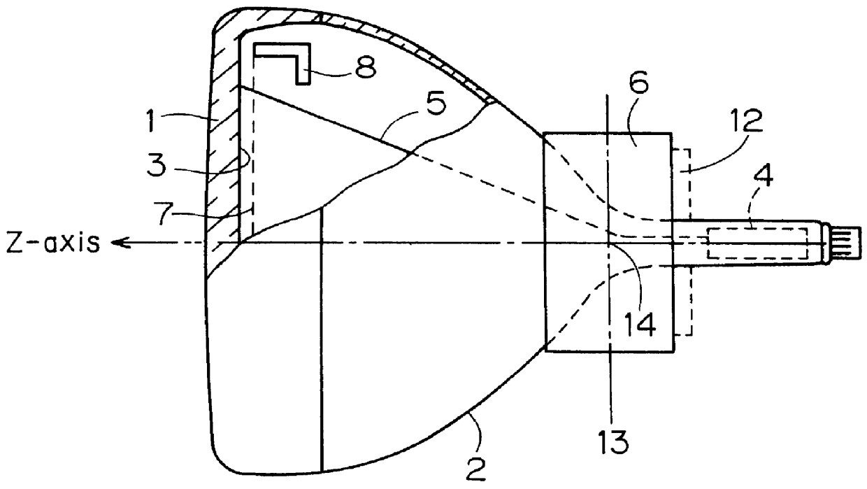
A first preferred embodiment of the present invention will now be described with a picture tube having a diagonal dimension of 51 cm. The picture tube device of the first preferred embodiment shown in FIG. 1 has the same structure as the conventional picture tube device shown in FIG. 21 except in the shape of the panel 1, the deflection yoke 6, and an auxiliary coil 12 added as needed. Specifically, in FIG. 1, 1 denotes a panel forming the envelope of the color picture tube, 2 denotes a funnel forming the envelope of the color picture tube (CRT) together with the panel 1, 3 denotes a phosphor screen formed by arranging red, blue, and green phosphors in order on the inside surface of the panel, 4 denotes an electron gun, 5 denotes the electron beam emitted from the electron gun 4, 6 denotes a deflection yoke for electromagnetically deflecting the electron beam 5, and 7 denotes a tension-type shadow grille serving as a color-selecting electrode. The structure of t...


PUM


Abstract

An object is to remove unnaturalness of the picture caused by inferior flatness of the apparent screen and provide a safety-designed color picture tube device having a flatter apparent screen without deterioration of static strength of the picture tube. The upper half of the panel (the part above the Z-axis) shows the vertical-axis (V) section and the lower half (the part below the Z-axis) shows the horizontal-axis (H) section. The outside surface of the panel is in a convex form with respect to the Z-axis in the vertical-axis (V) section with a radius of curvature of ROV and is in a convex form with respect to the Z-axis in the horizontal-axis (H) section with a radius of curvature of ROH. The inside surface of the panel is in an almost linear form in the vertical-axis (V) section with a radius of curvature of RIV and is in a convex form with respect to the Z-axis in the horizontal-axis (H) section with a radius of curvature of RIH.

Description

1. Field of the InventionThe present invention relates to a color picture tube device having a tension-type shadow grille.2. Description of the Background ArtFIG. 21 is a partially sectional side view showing a conventional color picture tube device having a tension-type shadow grille. In FIG. 21, 1 denotes a panel forming the envelope of the color picture tube, 2 denotes a funnel forming the envelope of the color picture tube together with the panel 1, 3 denotes a phosphor screen formed by arranging red, blue and green phosphors in order on the inside surface of the panel, 4 denotes an electron gun, 5 denotes electron beam emitted from the electron gun, 6 denotes a deflection yoke for electromagnetically deflecting the electron beam 5, and 7 denotes a tension-type shadow grille serving as a color-selecting electrode.FIG. 22 shows the structure of the conventionally used tension-type shadow grille 7. In FIG. 22, 8 denotes a frame formed of a steel material such as stainless steel (S...

Claims


Application Information

Patent Timeline
Patent Type & Authority Patents(United States)
IPC IPC(8): H01J29/86
CPCH01J29/861H01J2229/862
Inventor NAKAMURA, KOJIINOUE, AKIRA
Owner THOMSON LICENSING SA
Why Eureka
Try Eureka