Casing for PC card

a pc card and shell technology, applied in the direction of casings/cabinets/drawers, casings/cabinets/drawers details, printed circuit structure associations, etc., can solve the problems of damage to the chips on the circuit board, affecting data transmission between the i/o card and the computer system, and not ensuring a complete seal along the perimeter of the shells

Inactive Publication Date: 2000-12-26
HON HAI PRECISION IND CO LTD
View PDF10 Cites 66 Cited by
  • Summary
  • Abstract
  • Description
  • Claims
  • Application Information

AI Technical Summary

Problems solved by technology

However, the high vibrating frequency and heat generated during the welding process may damage the chips on the circuit board.
However, such a process may not ensure a complete seal along th

Method used


Image

  • Casing for PC card
  • Casing for PC card
  • Casing for PC card

Examples


Embodiment Construction

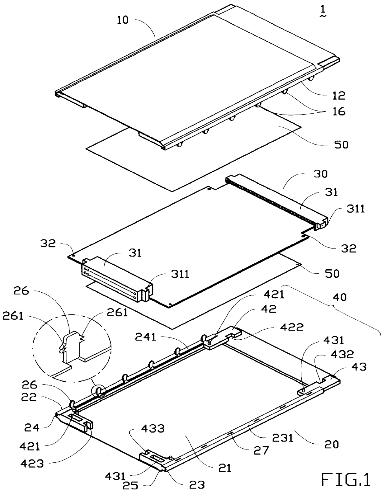
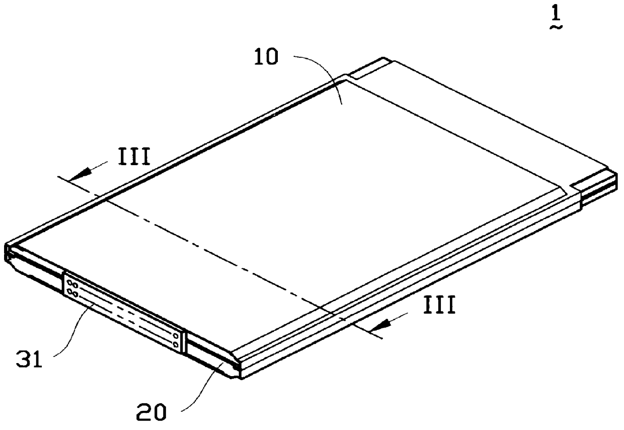
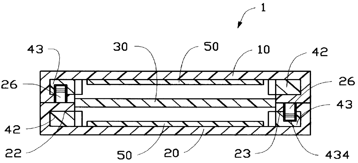
Referring to FIG. 1, a casing 1 in accordance with the present invention includes an upper half 10 and a lower half 20. The upper and lower halves 10, 20 have the same configuration thereby only the lower half 20 will be described in detail. The lower half 20 is directly stamped from a metal sheet and has a rectangular shape. The lower half 20 defines a recess 21 in a central region between first and second longitudinal sides 22, 23 thereof. A first retaining groove 24 and a second retaining groove 25 are respectively defined along the first and second longitudinal sides 22, 23. The first retaining groove 24 forms a plurality of spaced clipping tabs 26 extending vertically from a sidewall 241 thereof. Each clipping tab 26 is formed with barbs 261 extending from both sides thereof.

The second retaining groove 25 defines a plurality of retaining receptacles 27 in a sidewall 231 thereof. Each receptacle 27 is arranged to align with a corresponding clipping tab 16 on the first retaining ...


PUM


Abstract

A casing for enclosing a circuit board comprises pair of symmetrical halves assembled together. Each said half forms plurality of retaining means on a first longitudinal side thereof and plurality of receiving means at a second longitudinal side opposite said first longitudinal side whereby said halves are fixedly assembled together by the interlocking engagement between said retaining means and said receiving means.

Description

The present invention relates to a casing, and particularly to a casing for enclosing a circuit board such as a printed circuit board therein and having two halves thereof. Each half has symmetrical retaining means and receiving means interlocked together to ensure a reliable seal along the perimeter between the upper and lower halves.DESCRIPTION OF THE PRIOR ARTI / O cards provide all the functional options and flexibility of conventional expansion cards except that the I / O card is encased within a thin, compact unit facilitating insertion and withdrawal from a connecting device such as an I / O card connecting cartridge. The I / O card may carry a great deal of data accessed by the computer system such as a lap top computer.The conventional I / O card includes upper and lower shells interlocked together. Each shell further includes an insulating frame for positioning a circuit board together with a connector encapsulated within the shells. Normally the shells are made from a metal sheet f...

Claims


Application Information

Patent Timeline
IPC IPC(8): H05K5/02
CPCH05K5/0269
Inventor FUN, JONESWANG, KUO-CHENGWANG, STEVEN
Owner HON HAI PRECISION IND CO LTD
Why Eureka
Try Eureka