Building air conditioning system using geothermal energy

a building air conditioning and geothermal energy technology, applied in the direction of domestic cooling apparatus, greenhouse gas reduction, heating types, etc., can solve the problems of insufficient utilization of geothermal energy for air conditioning, inability to consider humidity control and air cleaning of air from outside, and extreme limitations of heat conduction using geothermal energy

Inactive Publication Date: 2001-09-25
GEO POWER SYST
View PDF28 Cites 69 Cited by
  • Summary
  • Abstract
  • Description
  • Claims
  • Application Information

AI Technical Summary

Problems solved by technology

In the cooling apparatus or the like described above, since air heat-exchanging with geothermal energy is merely performed during the process of moving air through the inside of the pipe, effect of heat conduction using geothermal energy is limited extremely and it has been extremely insufficient as utilization of geothermal energy to air conditioning.
Moreover, in the cooling apparatus described above, merely air from the outdoors is heat-exchanged with geothermal energy, and humidity control and air cleaning for air from outdoors cannot be considered.

Method used


Image

  • Building air conditioning system using geothermal energy
  • Building air conditioning system using geothermal energy
  • Building air conditioning system using geothermal energy

Examples


first embodiment

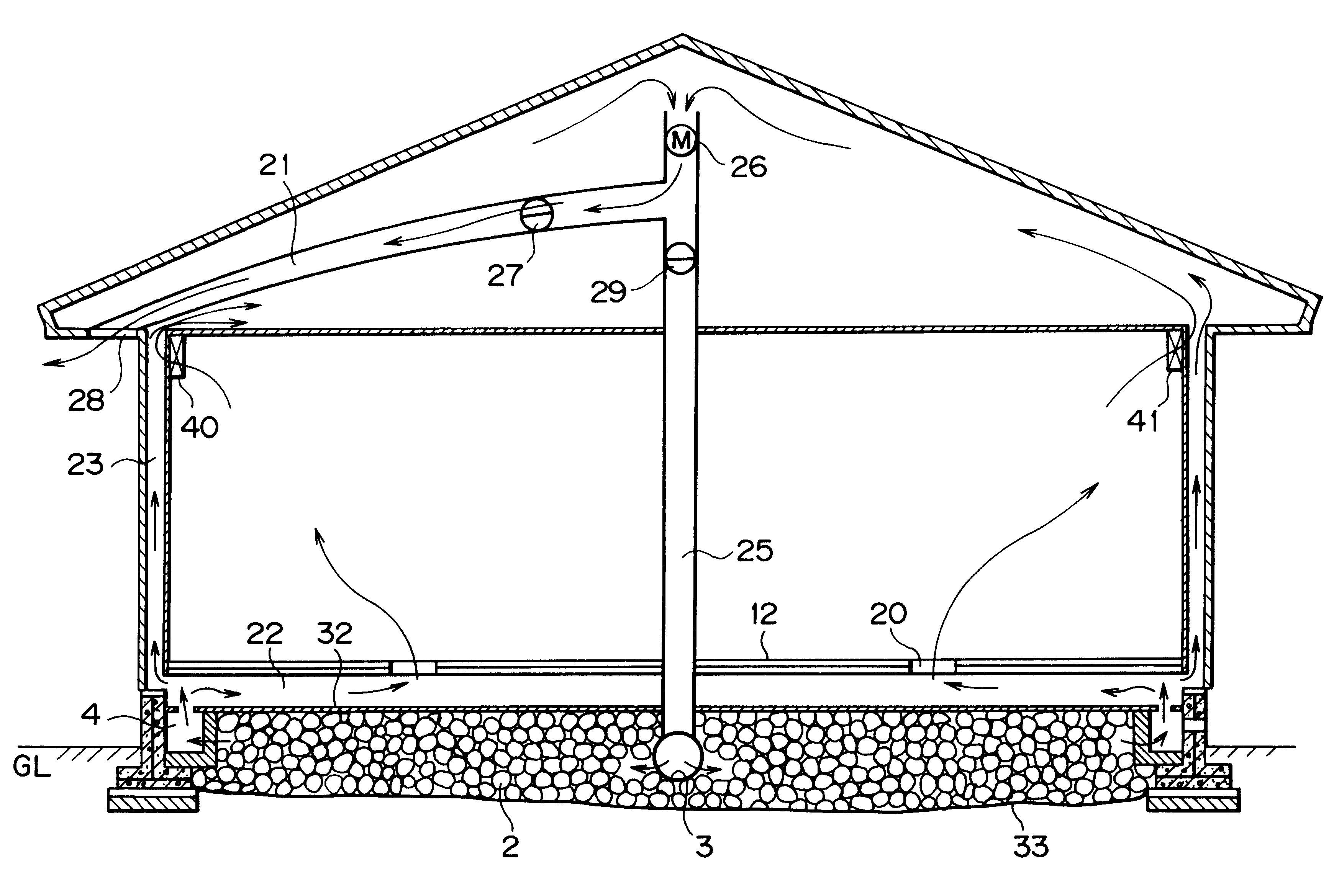
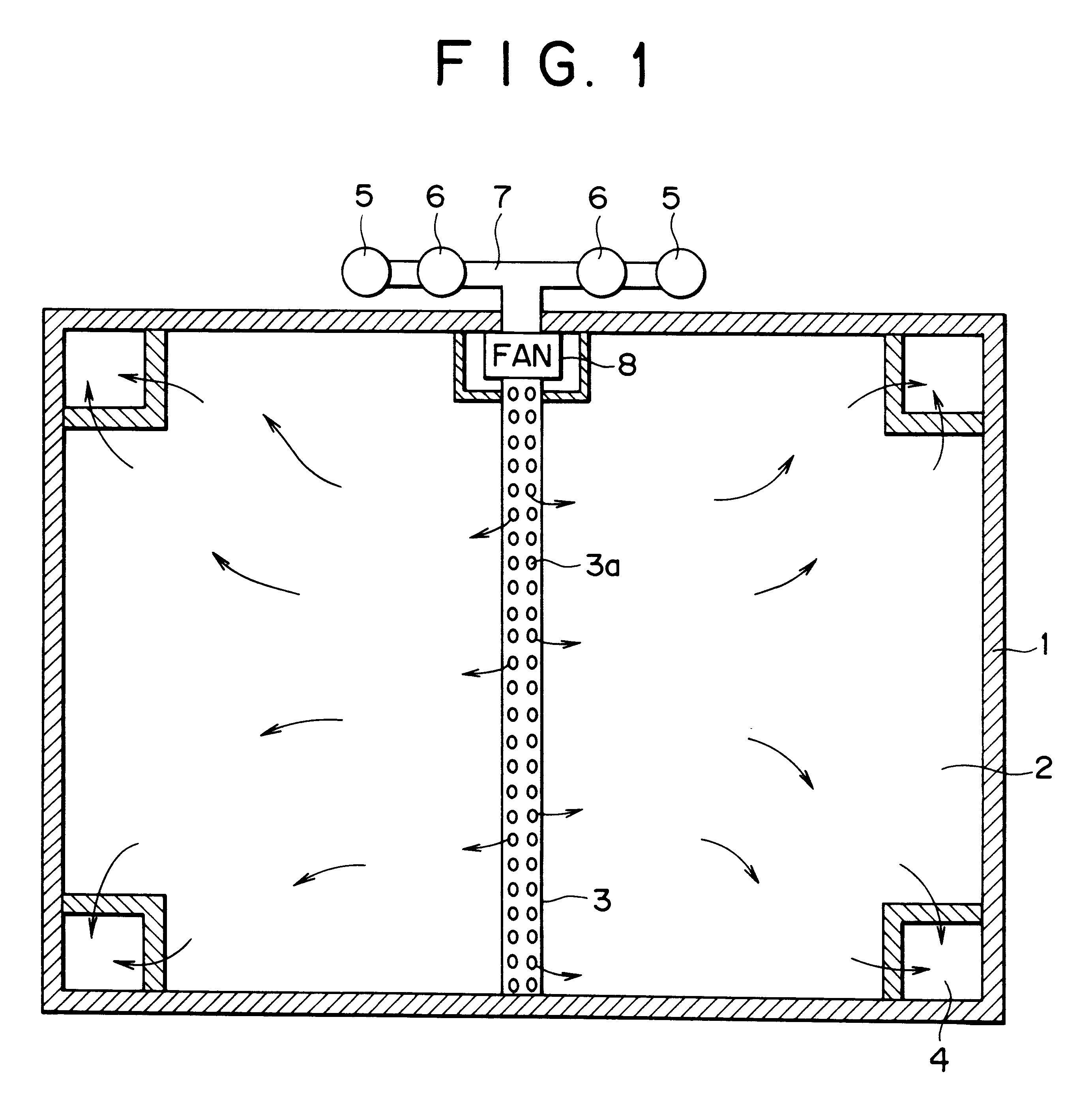
FIG. 1 is a horizontal sectional view for illustrating a first embodiment according to the invention. Referring to FIG. 1, a reference numeral 1 is an inverted T-shaped foundation of the building made of concrete in a cross section, which foundation is formed on an outer periphery of a building, and a reference numeral 2 is a cobble stone layer installed under the floor of the building (the individual cobble stone is omitted in illustration in FIG. 1) provided by filling a number of cobble stones within a space under the floor surrounded by this foundation 1, a floor of the building and the ground. For example, height of the cobble stone layer under the floor 2 is about 400 mm.

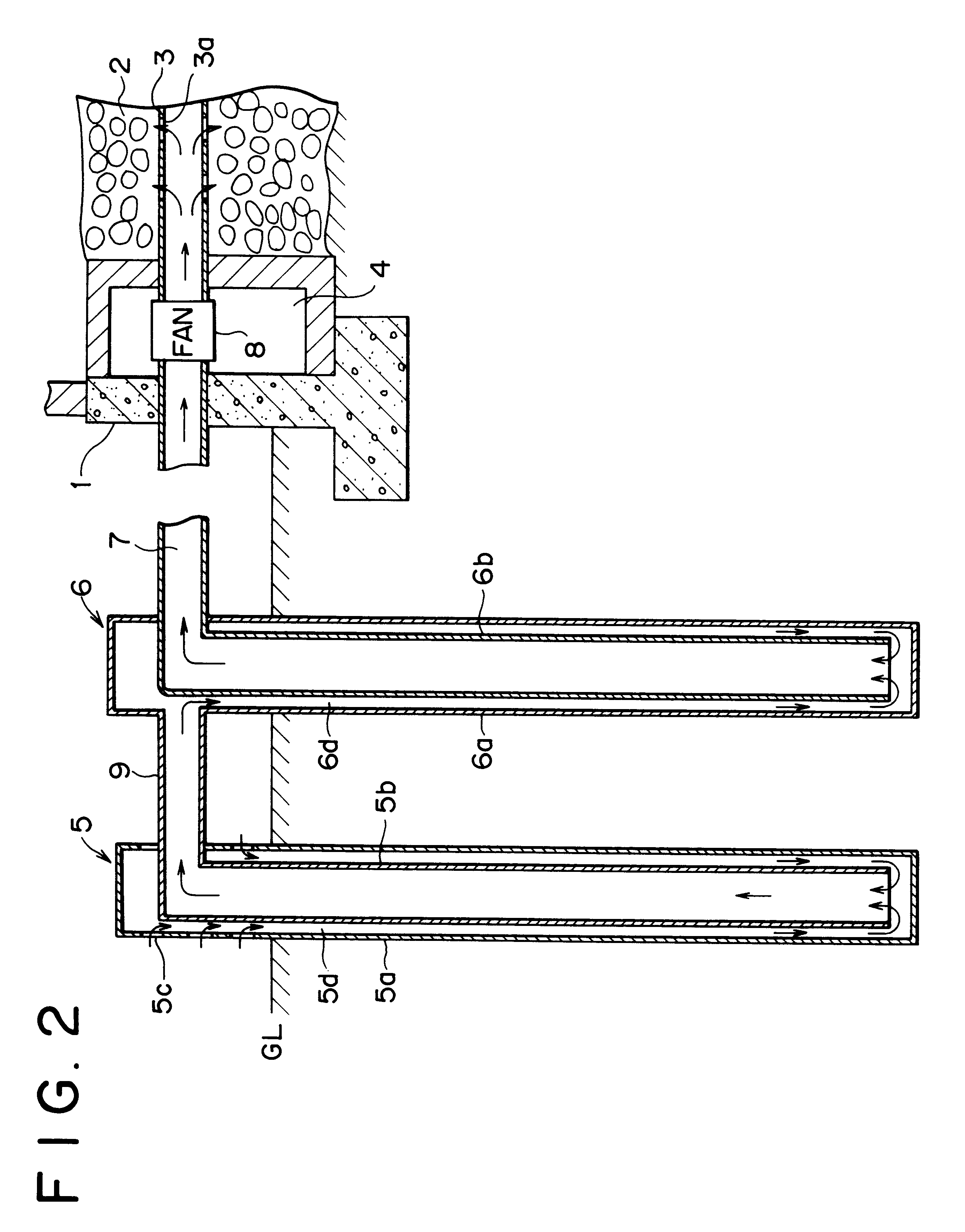
Moreover, in FIG. 1, a reference numeral 3 is a perforated pipe which is inserted into the approximately central portion of the inside of the cobble stone layer under the floor 2 and on which numerous holes 3a are formed. Air from underground pipes 5 and 6 described below is introduced into this perforated pip...

second embodiment

Therefore, even though, in general, it is said that thermal conductivity of the pipe made of plastic is low as compared with that of the pipe made of metal, since the outer pipe 51 is formed widely in the surface area and thinly in thickness as mentioned above, geothermal energy can be transmitted to the inside of the outer pipe 51 easily despite of using the wall made of plastic in the

Moreover, a plurality of openings (holes) 51a for allowing air from the outdoors to flow thereinto are formed on the upper of the spiral pipe for the outside 51 in FIG. 8(a).

Moreover, a reference numeral 52 is a spiral-shape belt made of metal such as aluminum or plastic in FIG. 8(a). This spiral-shape belt 52 is formed by forming an elongate belt-shaped (or ribbon-shaped) sheet made of aluminum into a spiral shape (a coil shape). This spiral-shape belt 52 is used in a manner to be arranged on the inside of the outer pipe 51 so as to contact with the inner wall surface of said outer pipe 51.

Therefore,...


PUM


Abstract

A building air conditioning system using geothermal energy comprising an underground pipe being buried underground for transmitting geothermal energy from the underground to air from the outdoors and for controlling humidity of said air and cleaning said air, a cobble stone layer constituted by filling numerous cobble stones in a space under the floor of a building for introducing air from said underground pipe to heat-exchange this introduced air with geothermal energy stored therein and to control humidity of said air and to clean said air, and air supply means for supply air from said cobble stone layer to an inside of a room of the building.

Description

1. Field of the InventionThis invention is related to a building air conditioning system using geothermal energy capable of applying to a building such as a detached dwelling house, a multiple dwelling house and a building.2. Description of the Prior ArtHeretofore, an air-conditioning system using geothermal energy has been proposed. For example, it have been disclosed a cooling apparatus or the like coupling a fixture under a floor of a dwelling house and a fixture on the ground of the outdoors by a pipe formed in the ground and adapted to transmit geothermal energy to air from the outdoors in the ground during the process that air is passing through the pipe from the outdoor and to supply the heat-exchanged air into the dwelling house in Japanese Patent Application Publication No. 60149 of 1982.In the cooling apparatus or the like described above, since air heat-exchanging with geothermal energy is merely performed during the process of moving air through the inside of the pipe, e...

Claims


Application Information

Patent Timeline
Patent Type & Authority Patents(United States)
IPC IPC(8): F24D11/00F24F5/00
CPCF24D11/006F24F5/0046F24F5/005F24J3/084F28D20/0052F24F2005/0057Y02B10/20Y02E60/142Y02B30/547Y02E10/125F24J2002/4603Y02B10/40Y02E70/30Y02B10/24F28F1/08Y02A30/272F24T10/17F24S2080/05Y02B30/54Y02E10/10Y02E60/14
Inventor HASHIMOTO, TOKO
Owner GEO POWER SYST
Why Eureka
Try Eureka