Clamping connector for spinal fixation systems

a technology of fixing system and connector, which is applied in the field of spinal fixation system, can solve the problems of unreliable durability, difficult to properly position the rod and the coupling elements, and the pedicle screws may not properly align with the longitudinal spinal rod

Inactive Publication Date: 2002-07-02
HOWMEDICA OSTEONICS CORP
View PDF54 Cites 163 Cited by
  • Summary
  • Abstract
  • Description
  • Claims
  • Application Information

AI Technical Summary

Problems solved by technology

Due to anatomical variations, pedicle screws may not properly align with the longitudinal spinal rods.
These teachings, however, have generally been complex, and unreliable with respect to durability.
The considerable drawback associated with the prior art systems include complexity, difficulty properly p

Method used


Image

  • Clamping connector for spinal fixation systems
  • Clamping connector for spinal fixation systems
  • Clamping connector for spinal fixation systems

Examples


Embodiment Construction

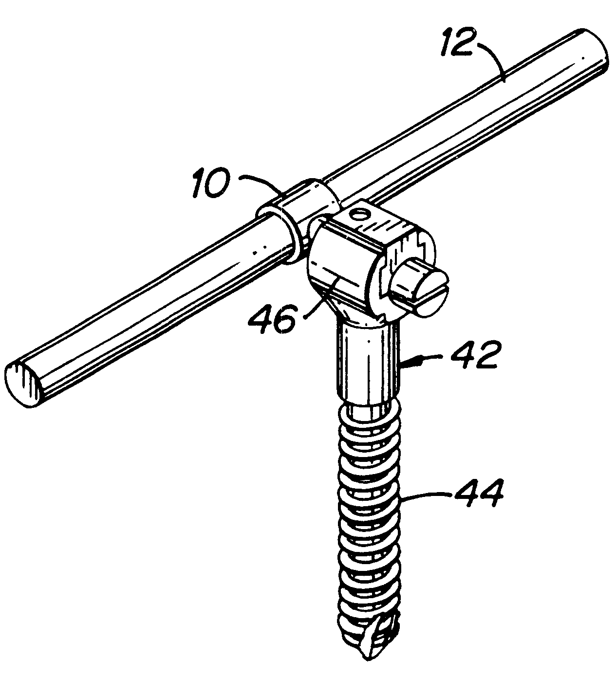
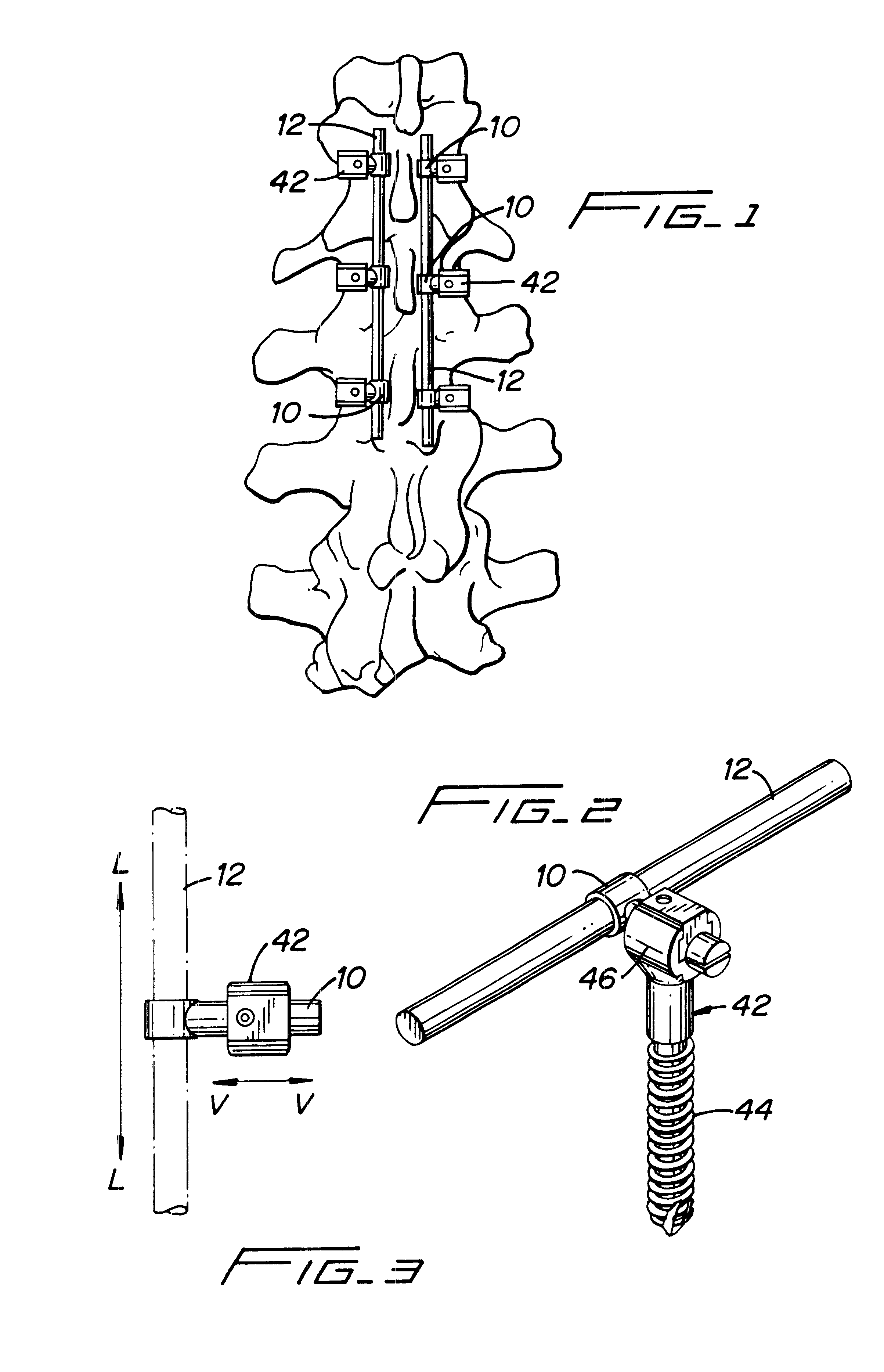
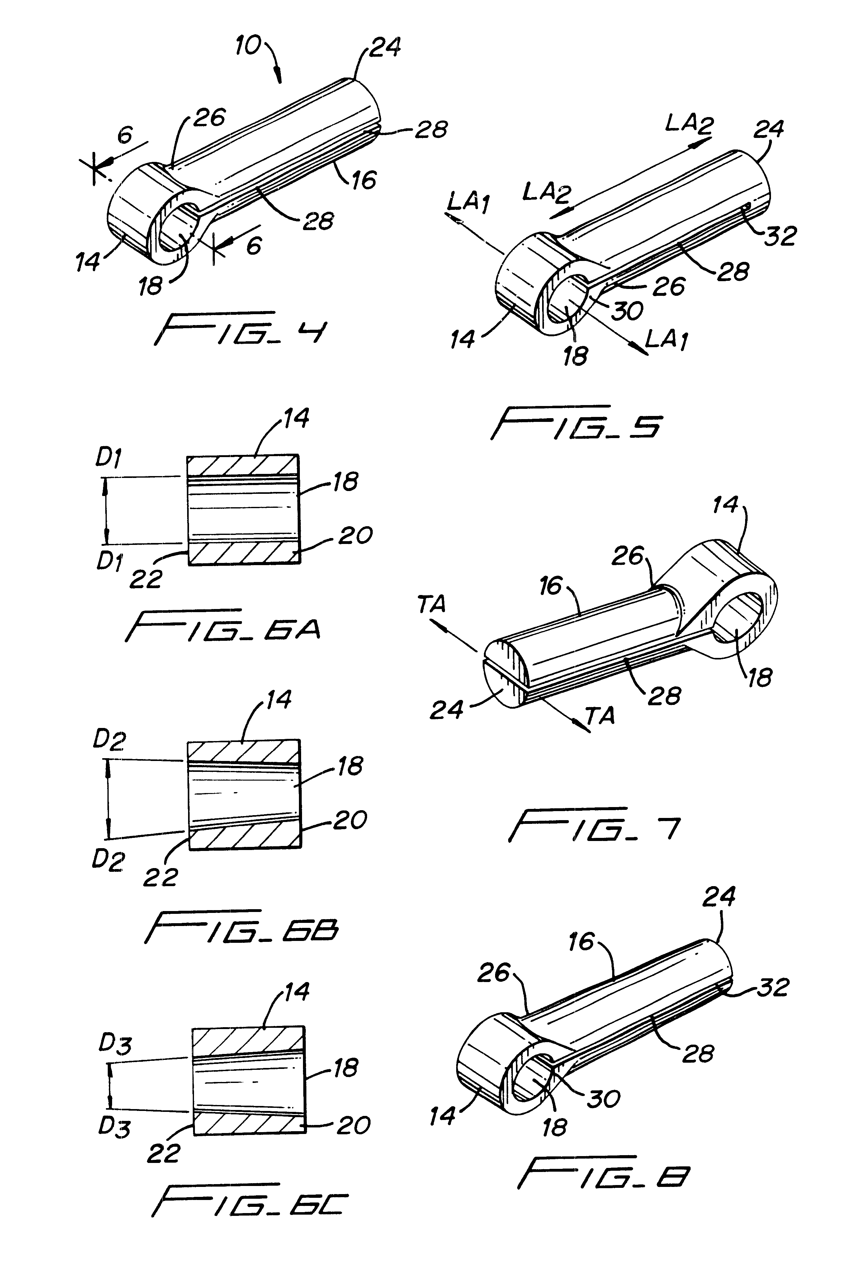
The present invention is directed to a one piece connector 10 that is used in spinal fixation systems such as the one shown in FIG. 1. Spinal fixation systems typically include spinal rods 12 and pedicle screws 42 or bone bolts (not shown). The one piece connector 10 includes a body portion 14 and a leg portion 16 (FIGS. 4 and 7). Body portion 14, in a preferred embodiment is generally cylindrical in shape with a longitudinal through bore 18 that has a longitudinal axis LA1--LA1, as shown in FIG. 5. However, body portion 14 can also have other shapes, such as for example, a spherical, oval or cubic shape. Bore 18 has a first end 20 and a second end 22 and an inside diameter D1--D1 (FIG. 6A) that in one embodiment is a constant dimension along the longitudinal axis LA1--LA1 from first end 20 to second end 22. Alternatively bore 18 can taper from a smaller inside diameter at first end 20 to a larger inside diameter D2--D2 at end 22 as shown in FIG. 6B or conversely bore 18 can taper f...


PUM


Abstract

The present invention is directed to one piece connector for connecting angularly misaligned implanted pedicle screws to transverse spinal rods in spinal fixation systems. The body portion includes a bore having an inside diameter and a longitudinal axis, with the longitudinal axis of the bore being positioned perpendicular to the longitudinal axis of the leg portion. The leg portion includes a slot placed through a section of the leg portion, along the transverse axis of the leg portion and parallel to the longitudinal axis of the leg portion. The slot intersects the bore of the body portion perpendicular to the longitudinal axis of the bore. The slot allows the one piece connector to be securely clamped around a longitudinal spinal rod when a pedicle screw is implanted at variable distances from the longitudinal spinal rod. The one piece connector allows for angular misalignment of an implanted pedicle screw in relation to a longitudinal spinal rod and the one piece connector, and for the attachment of the one piece connector to both the longitudinal spinal rod and to the implanted pedicle screw with a single locking mechanism when the one piece connector is used in a spinal fixation system.

Description

1. Field of the InventionThe present invention relates to spinal fixation systems for use in the treatment of spinal deformities and more particularly to a clamping connector for attaching angularly misaligned pedicle screws to transverse spinal rods in spinal fixation systems.2. Description of the Prior ArtSurgeons treat spinal disorders with spinal fusion augmented with longitudinal spinal rods connected to the spine with lamina hooks or pedicle screws. Such "rod assemblies" generally comprise one or two spinal rods and a plurality of screws inserted through the pedicles and into their respective vertebral bodies. The screws are provided with coupling elements, for coupling the elongate rod to the screws. The rods extends along the longitudinal axis of the spine, coupling to the plurality of screws via their coupling elements. The aligning influence of the rod forces the spine to which it is affixed, to conform to a more proper shape.Due to anatomical variations, pedicle screws ma...

Claims


Application Information

Patent Timeline
IPC IPC(8): A61B17/70A61B17/58
CPCA61B17/7037A61B17/7038A61B17/7041
Inventor LIN, CHIH-INICHOLS, DAVID
Owner HOWMEDICA OSTEONICS CORP
Why Eureka
Try Eureka