Overvoltage protection magazine

a protection magazine and overvoltage protection technology, applied in the direction of overvoltage protection resistors, emergency protection arrangements for limiting excess voltage/current, coupling device connections, etc., can solve the problems of inaccessibility or only with difficulty of the individual contacts of the junction module, the solution being a disadvantage in space requirements, and the design of each subassembly needs to be relatively complicated

Inactive Publication Date: 2004-11-23
QUANTE AG
View PDF20 Cites 20 Cited by
  • Summary
  • Abstract
  • Description
  • Claims
  • Application Information

AI Technical Summary

Benefits of technology

This combination in accordance with the invention does away with the known configuration of a rack-mounted junction block and an overvoltage protection magazine plugged into the junction block. Instead, in accordance with the invention the overvoltage protection magazine is now rack-mounted on which the junction zone is front mounted so that the combination of the two cited components has a low profile and thus takes up little room in the critical direction, namely in the vertical direction of a distribution point. In the depth direction of the distribution point the room taken up is less critical so that the invention in this respect results in no serious disadvantages.
To facilitate inserting the surge arresters in the magazine in accordance with the invention it is good practice when this is done from below, from above or partly from above and partly from below, for example alternatingly from above and below, it being particularly preferred when the surge arresters are all insertable from below. As compared to being inserted from above this has the advantage that the conductors joined to the junction zone, which are usually routed at the top above the overvoltage protection magazine, do not obstruct replacing individual arresters. In this arrangement, however, it may also be provided for that recesses are provided at the top side of the magazine at each arrester location so that pressure can be exerted on the arrester from above by a suitable tool, for instance by a screwdriver, to facilitate removing the arrester from below. However, the arresters may also be plugged-in from above or alternatingly from above and below to thus achieve substantially the same advantages as aforementioned in combination with mounting from below. More particularly, recesses may be provided at the underside of the magazine in accordance with the invention for top-inserted surge arresters to facilitate removing the protection components in this situation, too. Basically the surge arresters may also be devised for rear insertion, this being particularly suitable when the magazine can be removed or swung out of its mounting position so that it is accessible from the rear.
For the mounting means especially the latching means, provided on the overvoltage protection magazine in accordance with the invention it is preferred that these are provided behind the junction zone as mountable on the overvoltage protection magazine in accordance with the invention and electrically connectable thereto so as not to obstruct work done on the junction zone by parts of the rack-mounting system in which the magazine in accordance with the invention can be mounted. Furthermore, it is preferred for the mounting means of the magazine that these are not only located in the mounting position behind the junction zone but also in a rear portion of the overvoltage protection magazine itself to thus enable, for example, the overvoltage protection magazine to be released to a certain extent from its usual mounting position whilst still remaining connected to the rack-mounting system and rendering the overvoltage protection components accessible for replacement.
For circuiting the overvoltage protection magazine in accordance with the invention in combination with a junction zone it is good practice to route all conductors to one side of the overvoltage protection magazine to thus make it particularly simple, for example, to swivel the overvoltage protection magazine about the side to which the conductors are routed so that greatly simplified access to the surge arresters, for example, in the swivelled-open position is provided.

Problems solved by technology

There is the problem with these plug-in overvoltage protection means that the conductors joined to the individual contacts of the junction module are inaccessible or accessible only with difficulty.
This, however, substantially increases the space taken up by the combination of the junction block and overvoltage protection magazine in the vertical direction, thus resulting in these solutions being a disadvantage as regards their space requirement.
With the distribution board subassembly as it reads from DE 44 23 339 C1 in which the individual surge arresters are designed for rear plug-in mounting at the operational service side the problem remains that each subassembly needs to be designed relatively complicated and it needs to be assured that it has rear access.

Method used


Image

  • Overvoltage protection magazine
  • Overvoltage protection magazine
  • Overvoltage protection magazine

Examples


Embodiment Construction

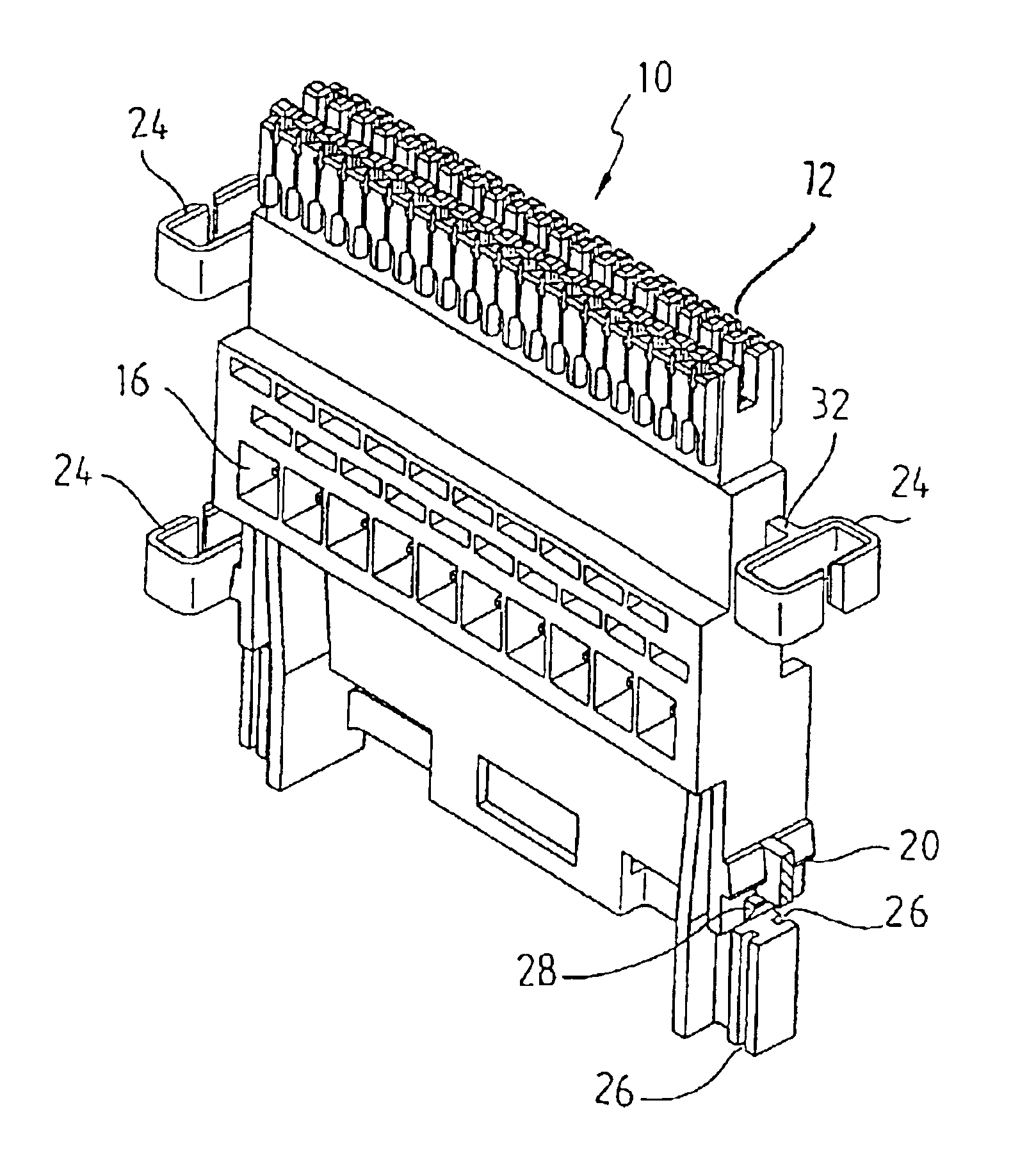
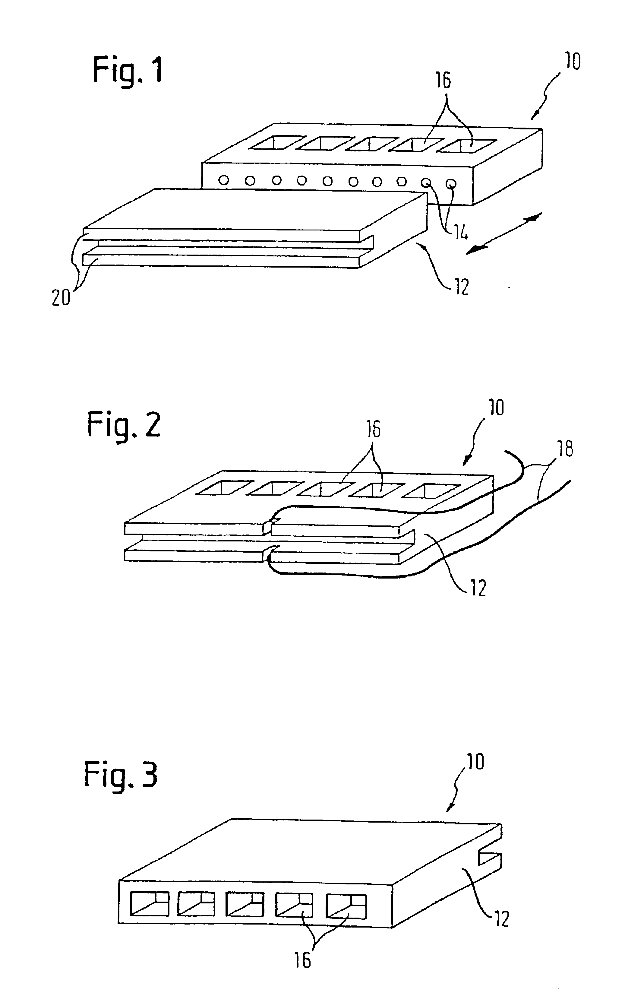
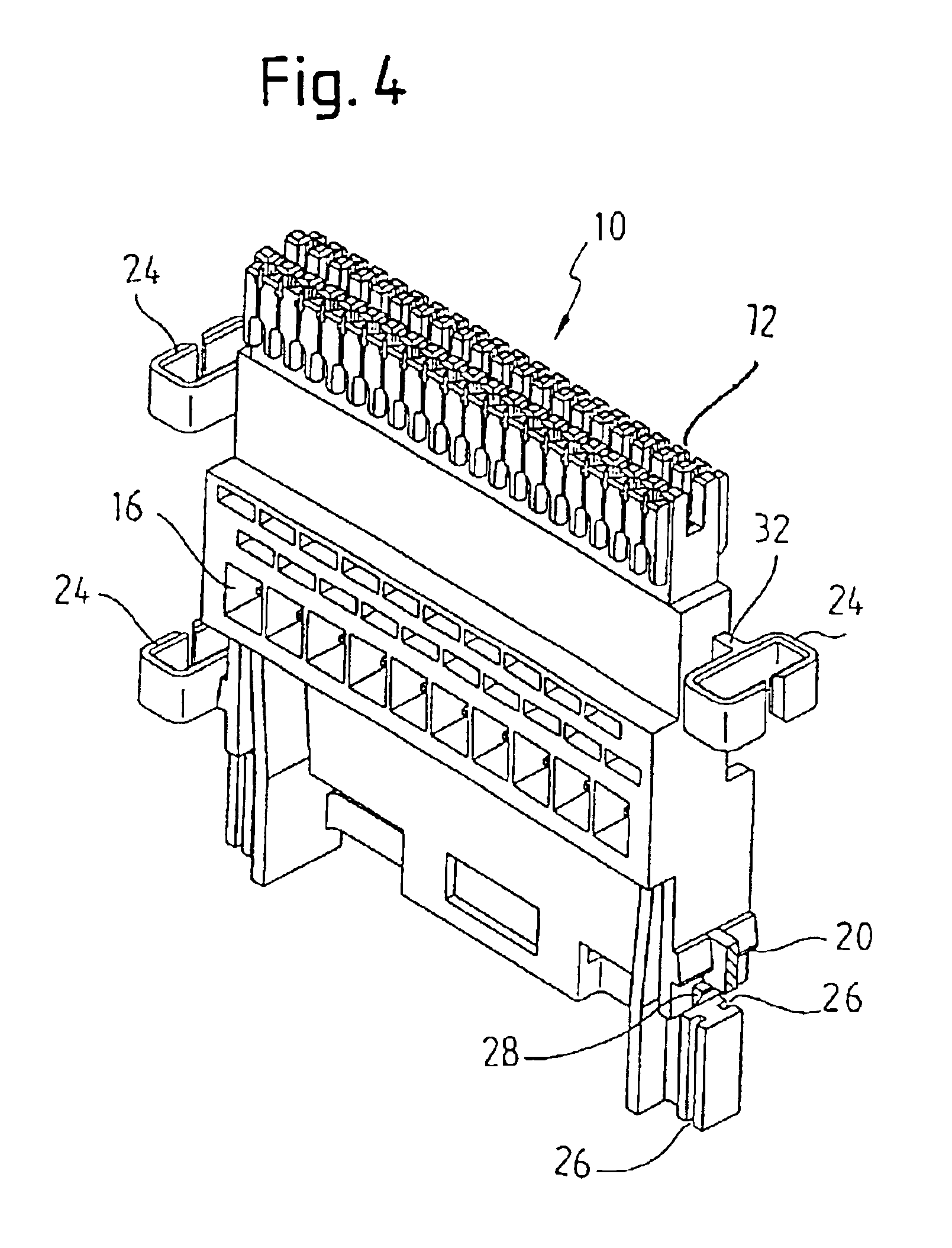
Referring now to FIG. 1 there is illustrated in a front view in perspective the overvoltage protection magazine 10 in accordance with the invention for front-mounting a junction zone 12 in accordance with the mounting position and electrically connectable via the contacts 14 as indicated. In accordance with the invention the overvoltage protection magazine 10 is mountable via mounting means (not shown) in a telecommunications rack-mounting system. Shown in FIG. 1 is the underside of the overvoltage protection magazine in which chambers 16 for receiving surge arresters are configured in accordance with a preferred embodiment, only five of which are shown in FIG. 1. In those embodiments discussed in more detail elsewhere, in which the chambers 16 are included alternatively or additionally on the top side of the magazine 10, the chambers 16 on the top side can be set forth as described with reference to the underside, one embodiment of which is illustrated in FIG. 1. Preferably these c...


PUM


Abstract

A telecommunications overvoltage protection magazine (10) permits in the mounting position direct mounting in a telecommunications rack-mounting system behind a junction zone (12) for cable conductors and electrical connection to the junction zone (12), the surge arresters being insertable in a mounting position from below, from above or partly from above and partly from below, more particularly alternatingly from above and below.

Description

1. Field of the InventionThe invention relates to a telecommunications overvoltage protection magazine.It is in this field that numerous junction modules mostly in the form of junction blocks are usually provided in suitable rack-mounting systems in distribution points, at least on the line side of which some means of overvoltage protection are needed as a rule.2. Prior ArtFor this purpose overvoltage protection plug-ins (cf. for example DE 39 21 227 C2) or overvoltage protection magazines (cf. subject matter of DE 30 14 796 C2) are known for front junction block mounting. There is the problem with these plug-in overvoltage protection means that the conductors joined to the individual contacts of the junction module are inaccessible or accessible only with difficulty.Solutions have been proposed to get round this problem (cf. DE 40 08 386 A1) by plugging-in the overvoltage protection magazines above the junction block in accordance with one mounting position of the latter. This, how...

Claims


Application Information

Patent Timeline
Patent Type & Authority Patents(United States)
IPC IPC(8): H01T4/06H02G15/10H01T4/00H02G15/117H04Q1/02H04Q1/14H02H9/02
CPCH01T4/06H04Q1/146H02G15/117H04Q1/14
Inventor OTTO, HANS-DIETERDENTER, FRIEDHELMGAERTNER, NORBERTBURMEISTER, KLAUS-DIETER
Owner QUANTE AG
Why Eureka
Try Eureka