Bale moving apparatus

a technology for moving equipment and bales, which is applied in the field of bale moving equipment, trailers for lifting, moving, handling bales, etc., can solve the problem of not teaching the advantage of positioning a rest surfa

Inactive Publication Date: 2005-01-11
NOUALY EMMANUEL P
View PDF10 Cites 17 Cited by
  • Summary
  • Abstract
  • Description
  • Claims
  • Application Information

AI Technical Summary

Benefits of technology

The present invention provides an improved bale moving apparatus including a generally horizontal tow frame with a linear support axle supported by a pair of opposing wheels. A tow bar provides a tow strut, a rest bar, and a winch. A bale support is pivotally joined to, and extends upwardly from the support axle assembly, and is rotatable between an upright attitude and a tilted-back attitude for securing a hay bale. A triangle formation of bale impaling spikes in mutually parallel disposition are used for impaling a hay bale at center and on two sides for securing the bale. The bale is pulling into the tilted-back attitude so as to enable resting the hay bale on the bale rest surface during travel. The rest surface is movable so as to enable placement of the hay bale's center of gravity on the vehicle.

Problems solved by technology

However, the prior art does not teach an advantageous positioning of a rest surface so that the CG of a lifted and transported bale is advantageously placed.

Method used


Image

  • Bale moving apparatus
  • Bale moving apparatus
  • Bale moving apparatus

Examples


Embodiment Construction

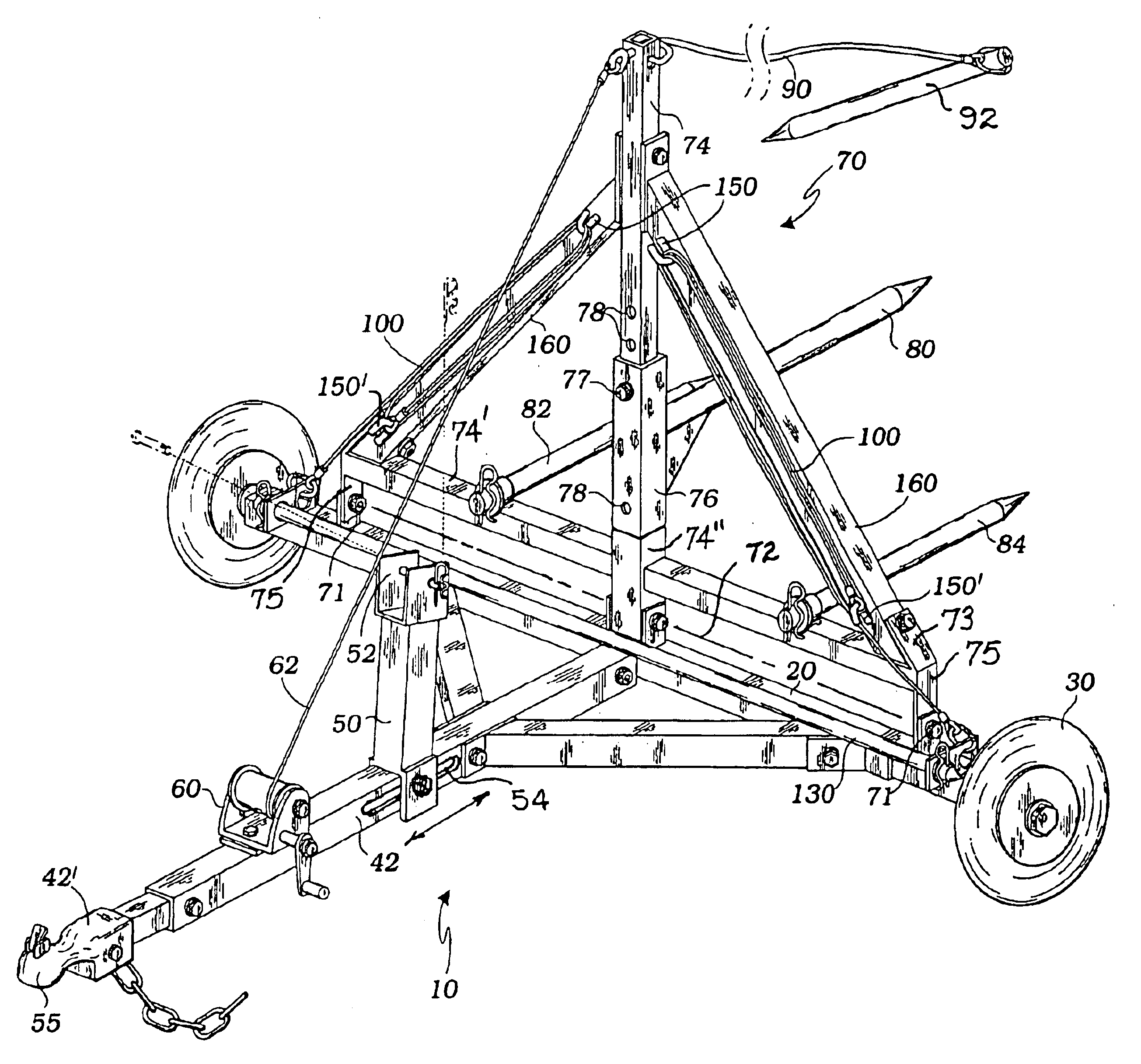
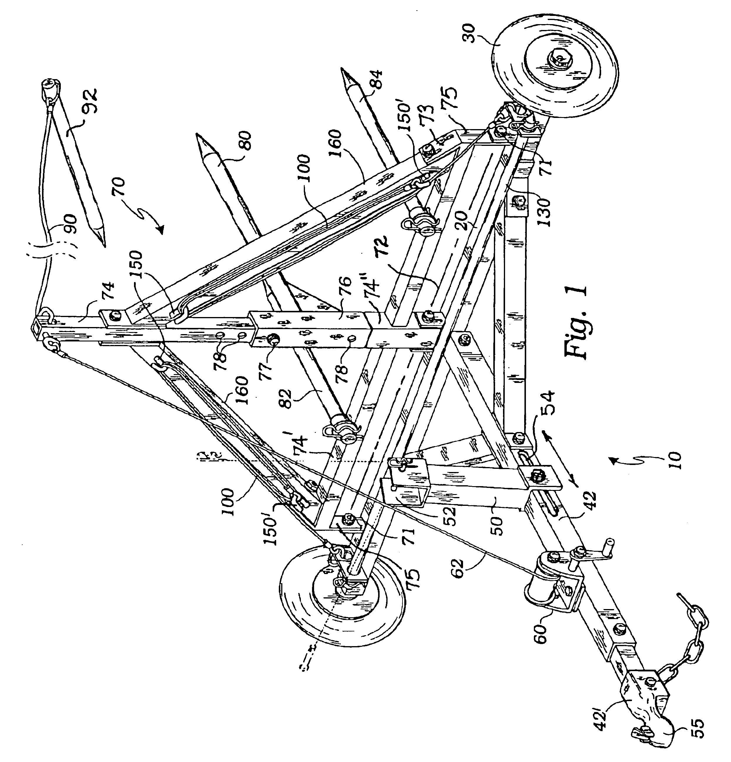
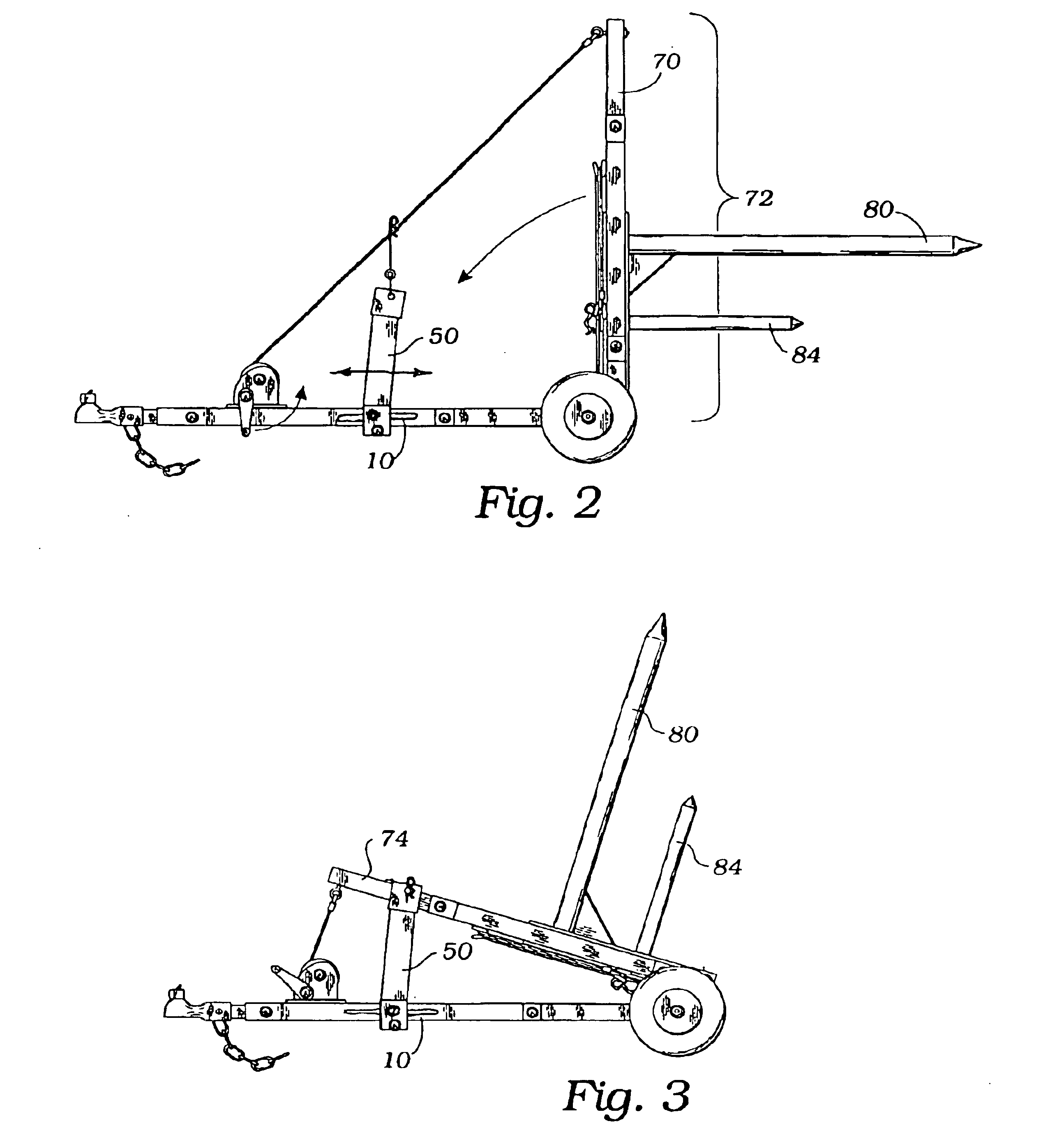
The above described drawing figures illustrate the invention, a bale moving apparatus comprising a generally horizontal tow frame 10 providing a linear support axle assembly 20 supported by a pair of opposing wheels 30 for moving the tow frame 10 over a terrain surface (not shown). Such a support axle assembly 20 may use any well-known automotive type axle assemblies type. Medially joined with the support axle assembly 20 is a tow bar assembly, providing a tow strut 42 which is preferably of square steel tubing and is welded or bolted to the support axle assembly 20, a medially placed rest bar 50 extending upwardly from the tow strut 42 and of similar construction, a winching means 60, preferably a hand crank, as shown in FIG. 1, or a motor driven winch (not shown), and a distal tow fixture 55 such as any such fixture commonly used for towing trailers and such. The described elements of this assembly are joined together using well-known fasteners and fastening techniques.

A bale supp...


PUM


Abstract

A bale moving apparatus provides a generally horizontal tow frame with a linear support axle supported by a pair of opposing wheels. A tow bar provides a tow strut, a rest bar, and a winch. A bale support is pivotally joined to, and extends upwardly from the support axle assembly, and is rotatable between an upright attitude and a tilted-back attitude for securing a hay bail. A triangle formation of bale impaling spikes in mutually parallel disposition are used for impaling a hay bale at center and on two sides for securing the bail. The bale is pulling into the tilted-back attitude so as to enable resting the hay bale on the bale rest surface during travel. The rest surface is movable so as to enable placement of the hay bale's center of gravity on the vehicle.

Description

INCORPORATION BY REFERENCEApplicant(s) hereby incorporate herein by reference, any and all U.S. patents, U.S. patent applications, and other documents and printed matter cited or referred to in this application.BACKGROUND OF THE INVENTION1. Field of the InventionThis invention relates generally to farm equipment drawn by a separate vehicle, and more particularly to a trailer for lifting, moving, handling, and unrolling bales of feed or bedding, especially those of circular conformation.2. Description of Related ArtThe following art defines the present state of this field:Hedgespeth, U.S. Pat. No. 4,348,148 describes a large round hay bale trailer having a fork lift cradle pivotally mounted on a two wheel trailer frame, the cradle being formed by pipe having a 90 degree vertical and horizontal bends to provide fork, back support and horizontal connecting elements. Laterally extending pipe sections welded to the cradle pipe provide pivotal bearings for a horizontal wheel axle pipe to ...

Claims


Application Information

Patent Timeline
Patent Type & Authority Patents(United States)
IPC IPC(8): A01D87/00A01D87/12
CPCA01D87/127A01D2087/128
Inventor NOUALY, EMMANUEL P.
Owner NOUALY EMMANUEL P
Why Eureka
Try Eureka