Power supply having multi-vector error amplifier for power factor correction

a power factor correction and multi-vector technology, applied in the direction of electric variable regulation, process and machine control, instruments, etc., can solve the problems of large power loss, increased input voltage, and increased power distribution system and transmission line stress, so as to increase the control bandwidth of the feedback loop, reduce gain, and rapid transient response

a power factor correction and multi-vector technology, applied in the direction of electric variable regulation, process and machine control, instruments, etc., can solve the problems of large power loss, increased input voltage, and increased power distribution system and transmission line stress, so as to increase the control bandwidth of the feedback loop, reduce gain, and rapid transient response

US6900623B2Inactive Publication Date: 2005-05-31SEMICON COMPONENTS IND LLC

Image

  • Power supply having multi-vector error amplifier for power factor correction
  • Power supply having multi-vector error amplifier for power factor correction
  • Power supply having multi-vector error amplifier for power factor correction

Examples


Embodiment Construction

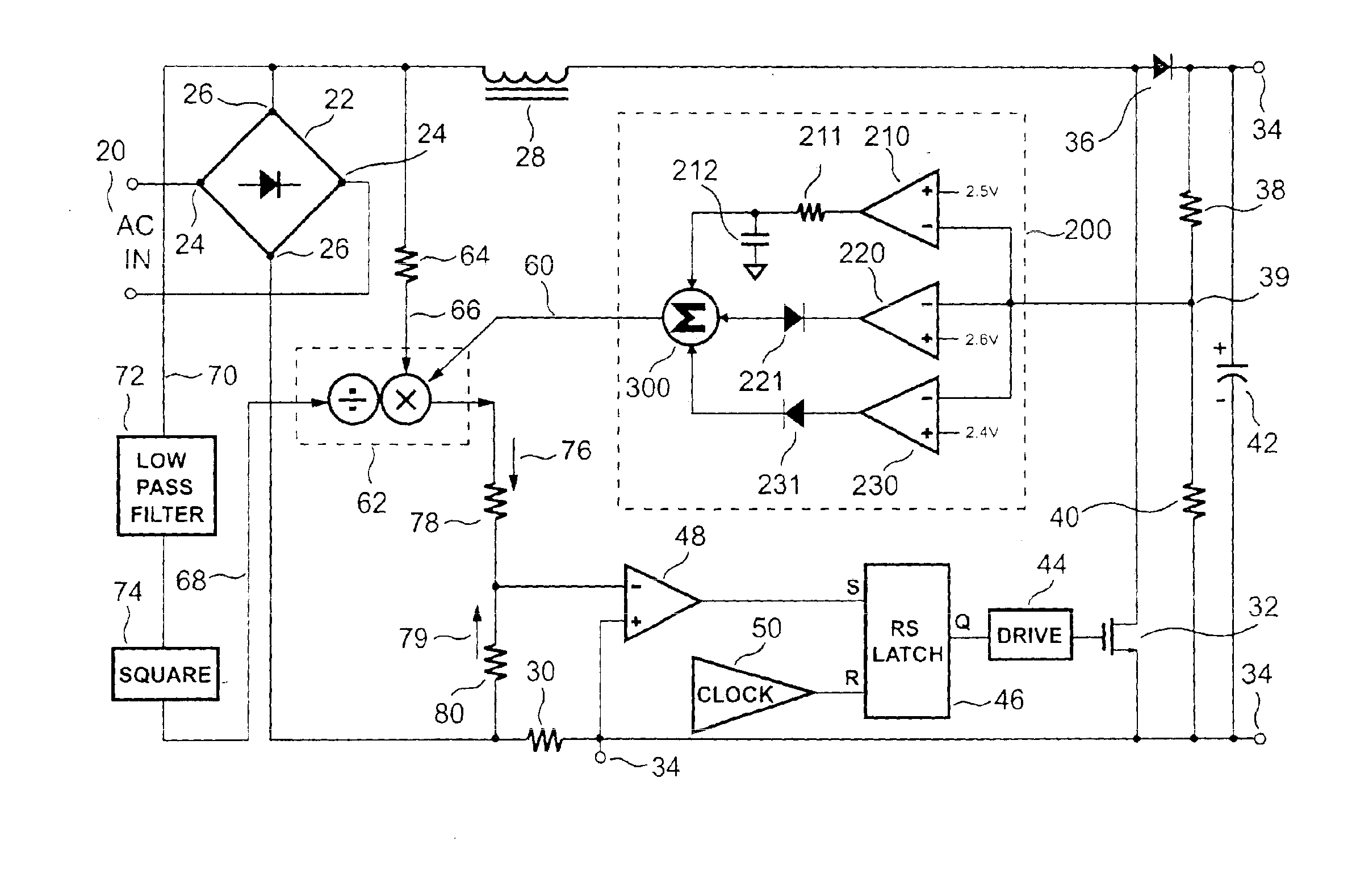
[0036]Referring now to the drawings wherein the contents are for purposes of illustrating the preferred embodiment of the invention only and not for purposes of limiting same, FIG. 4 shows a block diagram of a known regulated power supply with power factor correction.

[0037]In this circuit, a bridge rectifier 22 receives an AC input signal 20 at an AC input 24. An output 26 of the bridge rectifier 22 is connected to an inductor 28 and a current-sense resistor 30. The inductor 28 and the current-sense resistor 30 are connected together to form a loop, through a switch 32. The switch 32 may be any of several components, including a FET switch or some other type of known switching device.

[0038]When the control circuitry closes the switch 32, the voltage from the bridge rectifier 22 is applied to the inductor 28. The current passing through the inductor 28 starts to increase. Eventually, the switch 32 opens and the current flowing through the inductor 28 flows through a diode 36 to charg...


PUM


Abstract

A regulated power supply having power factor correction control includes a multi-vector error amplifier. The multi-vector error amplifier provides an error signal that is used to regulate a switching mechanism of the power supply. The multi-vector error amplifier acts to provide a low distortion error signal during steady-state operation, while responding rapidly and smoothly to sudden load changes.

Description

BACKGROUND OF THE INVENTION[0001]1. Field of the Invention[0002]The present invention generally relates to the art of power supplies and more particularly, to a regulated power supply with power factor correction (PFC) control.[0003]2. Description of the Related Art[0004]Regulated power supplies are used for power conversion in many applications, including computers, lighting ballasts, and telecommunications devices. Products consuming 70 watts or more generally require regulated power supplies with power factor correction, to reduce power loss and comply with environmental regulations. In these and other products where significant load variations are frequent, regulated power supplies capable of reacting rapidly to sudden load changes are especially desirable.[0005]Without power factor correction, an AC / DC power conversion system will draw current through the rectifier in sharp bursts, shown in FIG. 1B. These high peak currents cause significant power losses due to heat dissipation...

Claims


Application Information

Patent Timeline
31 May 2005
Publication
US6900623B2
IPC
G05F1/40; G05F1/56; G05F1/10; H02M7/00; H02M1/00; H02M1/42
CPC
H02M1/4225; Y02B70/126; H02M2001/4275; Y02B70/10; H02M1/4275
Inventors
YANG, TA-YUNG; LEU, YI-HSIN