Weight detecting device for microwave ovens

Active Publication Date: 2005-06-28
SAMSUNG ELECTRONICS CO LTD
View PDF6 Cites 0 Cited by
  • Summary
  • Abstract
  • Description
  • Claims
  • Application Information

AI Technical Summary

Benefits of technology

[0010]Accordingly, it is an aspect of the present invention to provide a weight detecting device for microwave ovens, which is designed to minimize a s

Problems solved by technology

However, the conventional weight detecting device has a problem that the guide plate 4 thereof surrounds the weight sensor 5, so a space to install the weight sensor 5 is increased and the size of the guide plate 4 is undesirably increased.
The conventional weight detecting device has another problem that th

Method used


Image

  • Weight detecting device for microwave ovens
  • Weight detecting device for microwave ovens
  • Weight detecting device for microwave ovens

Examples


Embodiment Construction

[0018]Reference will now be made in detail to the present preferred embodiment of the present invention, examples of which are illustrated in the accompanying drawings, wherein like reference numerals refer to like elements throughout.

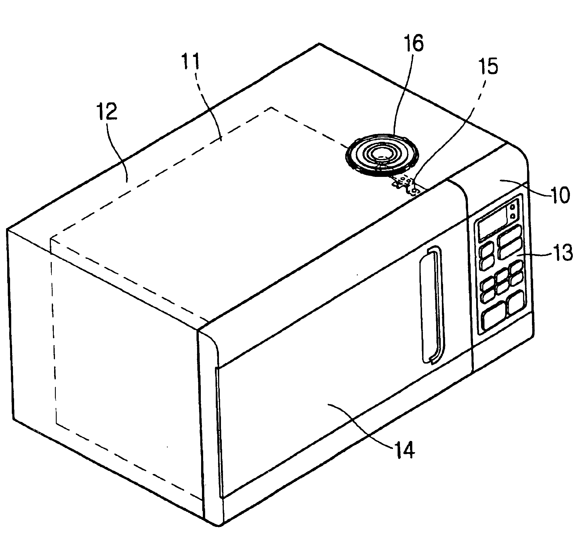
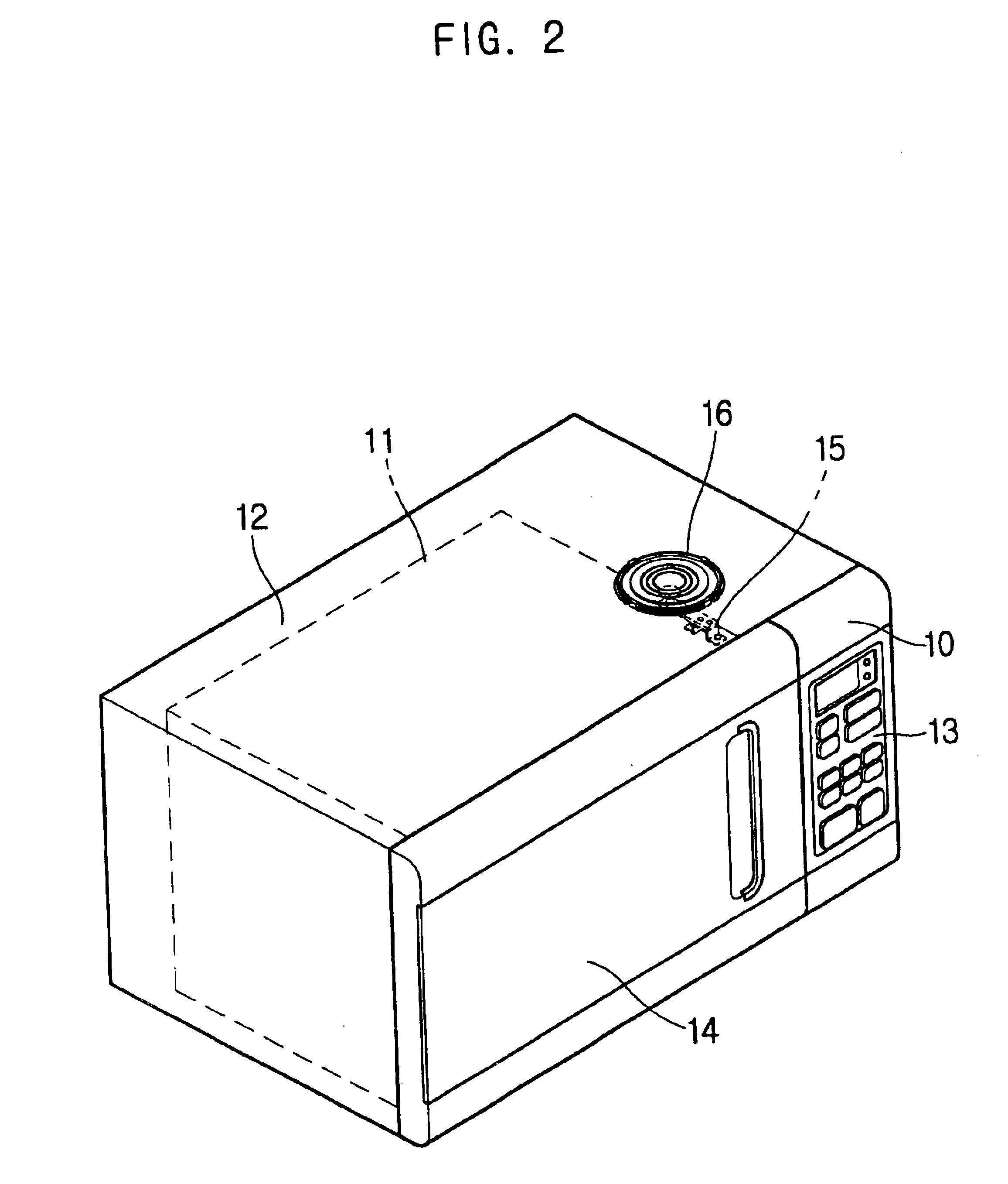
[0019]FIG. 2 is a perspective view of a microwave oven having a weight detecting device according to an embodiment of the present invention.

[0020]As illustrated in FIG. 2, a microwave oven 8 includes a machine room 10 in which a magnetron (not shown) irradiating microwaves is installed. The microwave oven 8 further includes an interior casing 11 partitioned from the machine room 10. The magnetron irradiates microwaves into the interior casing 11. An exterior casing 12 surrounds the interior casing 11 and defines the machine room 10 therein and maintains a predetermined gap between the interior and exterior casings 11 and 12.

[0021]A control panel 13 is mounted to a front of the machine room 10 to control an operation of the microwave oven 8. A door 14 i...


PUM


Abstract

A weight detecting device for microwave ovens is used to detect a weight of food placed on an exterior casing to minimize a space to install a weight sensor and to prevent heat from being transmitted from an interior casing through a top plate of the interior casing to the weight sensor. The weight detecting device includes a weight detecting unit and a support unit. The weight detecting unit is supported at an end thereof, and detects a weight according to a force applied to a free end thereof. The support unit supports the weight detecting unit at a position spaced apart from a top plate of an interior casing of a microwave oven.

Description

CROSS-REFERENCE TO RELATED APPLICATION[0001]This application claims the benefit of Korean Application No. 2003-1577, filed Jan. 10, 2003, in the Korean Intellectual Property Office, the disclosure of which is incorporated herein by reference.BACKGROUND OF THE INVENTION[0002]1. Field of the Invention[0003]The present invention relates, in general, to weight detecting devices for microwave ovens and, more particularly, to a weight detecting device for microwave ovens which is used to detect a weight of food placed on an exterior casing of a microwave oven.[0004]2. Description of the Related Art[0005]FIG. 1 is a side sectional view of a microwave oven having a conventional weight detecting device.[0006]As illustrated in FIG. 1, a microwave oven includes an interior casing 1 and an exterior casing 3. A guide plate 4 having a shelf shape is provided in a space defined between a top plate 2 of the interior casing 1 and the exterior casing 3. In the microwave oven of FIG. 1, the guide plat...

Claims


Application Information

Patent Timeline
IPC IPC(8): G01G19/56G01G19/52H05B6/68F24C7/02F24C15/00
CPCH05B6/6464G01G19/56F24C15/00
Inventor KIM, KYOUNG HOCHO, JAE MAN
Owner SAMSUNG ELECTRONICS CO LTD
Why Eureka
Try Eureka