Power system for a telecommunication facility

a technology for telecommunication facilities and power systems, applied in emergency supply, mechanical energy handling, fuel cells, etc., can solve the problems of increasing the current manner in which power is supplied to telecommunication facilities, and the rise of the cost of local electrical utility services in recent years

Active Publication Date: 2005-08-16
T MOBILE INNOVATIONS LLC
View PDF9 Cites 46 Cited by
  • Summary
  • Abstract
  • Description
  • Claims
  • Application Information

AI Technical Summary

Problems solved by technology

There are several disadvantages inherent in the current manner in which power is supplied to telecommunications facilities.
First, the cost of local electrical utility service has risen dramatically in recent years and, by all accounts, will continue to rise.
Thus, the cost of local electrical utility power is a large component of the facility's overall power expenses.
Clearly, the component cost of...

Method used


Image

  • Power system for a telecommunication facility
  • Power system for a telecommunication facility
  • Power system for a telecommunication facility

Examples


Embodiment Construction

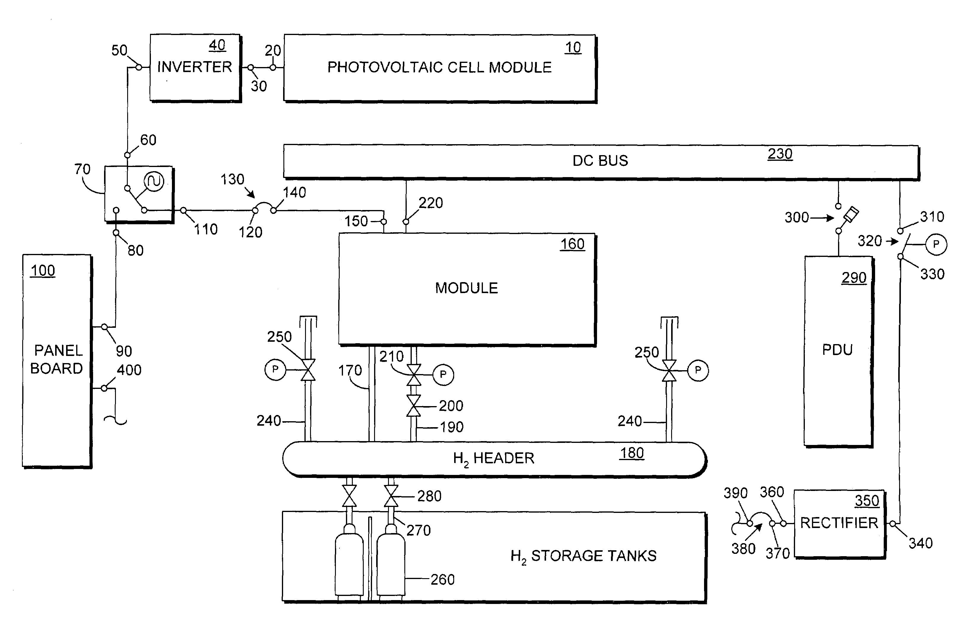
[0013]The present invention includes both a system and a method for providing reliable electrical power to a facility, and specifically to a telecommunications facility. The system provides redundant sources of electrical power including a number of hydrogen generator / proton exchange membrane cells and a number of photovoltaic panels. The system also includes a number of capacitors to provide power during the time required to switch between power sources. By employing these components, the system avoids the need for an array of batteries and is more cost efficient than current methods for providing power to telecommunications facilities.

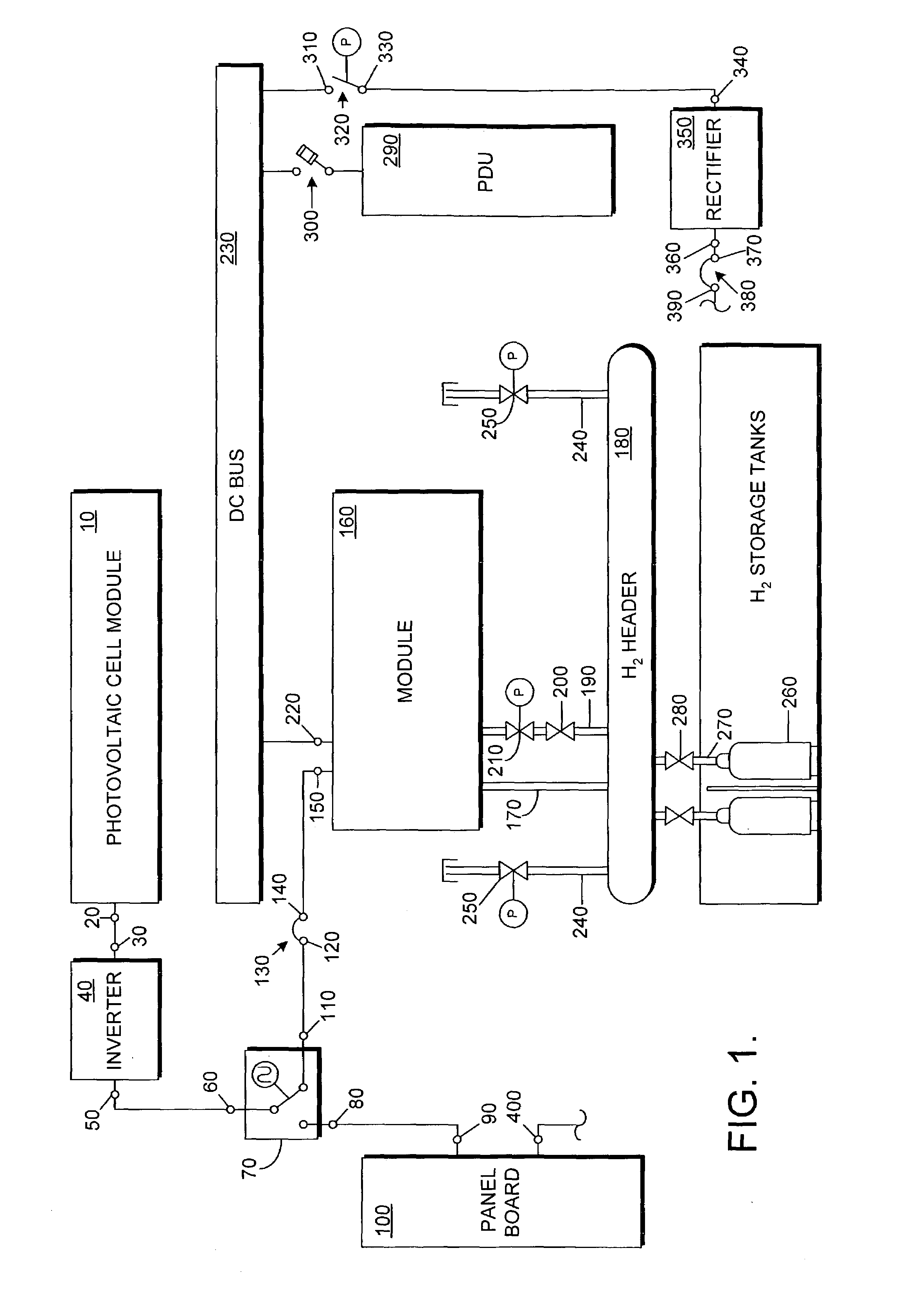
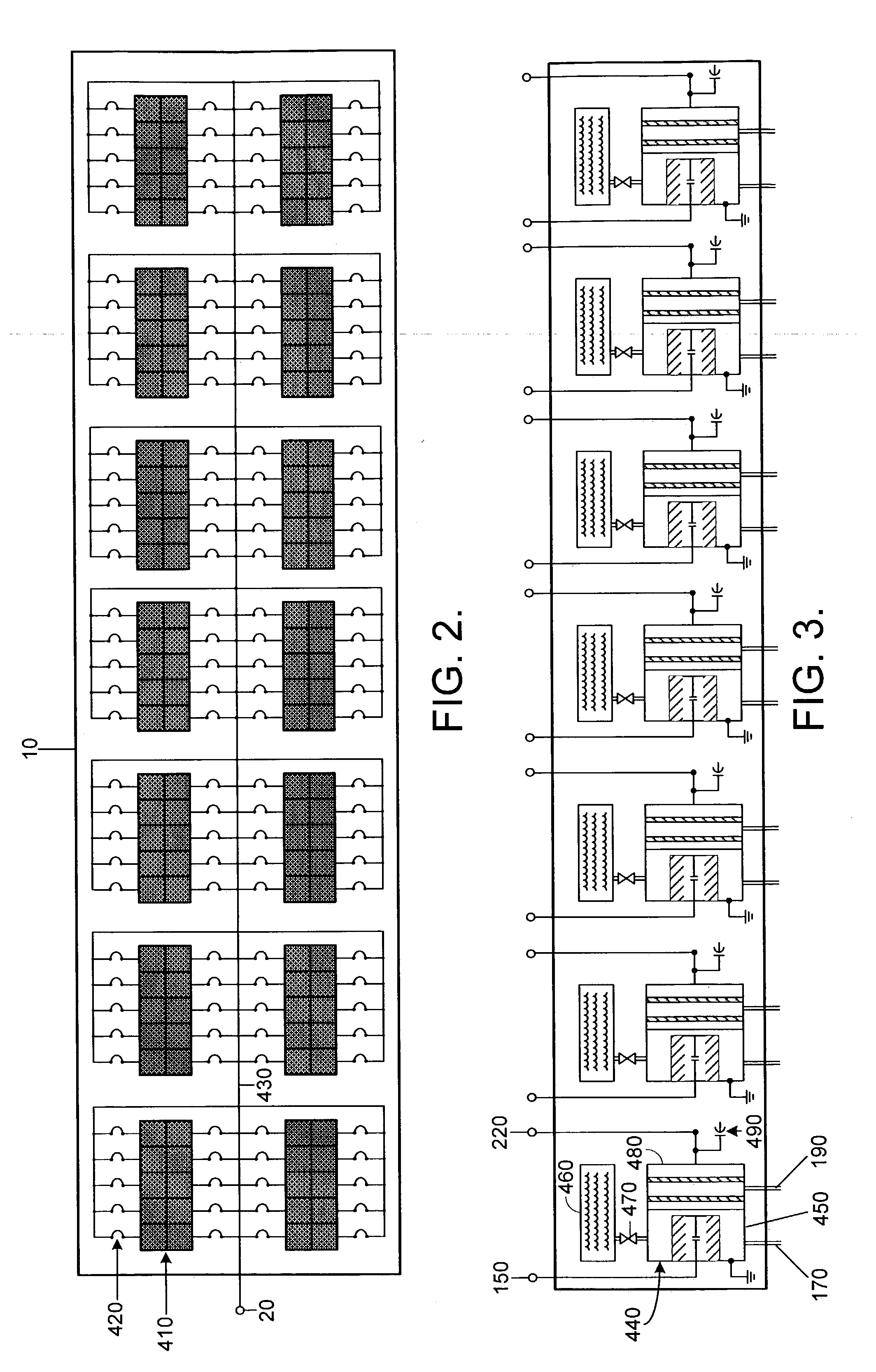
[0014]The present invention is best understood in connection with the schematic diagrams of FIGS. 1–3. In FIG. 1, the power system of the present invention initially comprises a photovoltaic cell module 10. It should be understood a photovoltaic cell is operable to convert light into DC electricity. Therefore, DC electricity is output from module 10 ...


PUM


Abstract

The present invention includes a power system that is designed to provide reliable electrical power to a facility, and specifically to a telecommunications facility. The system includes a number of proton exchange membranes (PEMs) adapted to provide DC power. The system is configured so that the PEMs receive fuel from a header that is supplied by a number of hydrogen generators. Storage tanks are also included to provide hydrogen to the header if the hydrogen generators fail. The hydrogen generators receive electricity initially from an array of photovoltaic panels. If the photovoltaic panels fail then AC power from a commercial utility is provided to the hydrogen generators. Finally, the system includes a number of super capacitors that are operable to maintain power during the time required to change between power sources.

Description

CROSS-REFERENCE TO RELATED APPLICATIONS[0001]None.STATEMENT REGARDING FEDERALLY SPONSORED RESEARCH OR DEVELOPMENT[0002]None.BACKGROUND OF THE INVENTION[0003]In general, this invention relates to a system for providing electrical power. More specifically, this invention is directed to a system particularly adapted to provide reliable electrical power for the operation of a remote telecommunications facility.[0004]Although it may be utilized in numerous applications, this invention is specifically adapted to provide power for the continuous operation of a remote telecommunications facility. With its core technology substantially composed of digital components, the telecommunications industry is heavily dependent on the continued supply of reliable electrical power. The critical nature of the functions performed by remote telecommunications facilities further emphasizes the need for a dependable power supply.[0005]Most telecommunications facilities rely on a commercial power utility fo...

Claims


Application Information

Patent Timeline
IPC IPC(8): H02J9/06H01M8/04H01M8/10
CPCH01M8/04089H01M8/04201H02J9/06H01M2008/1095H01M2250/10H01M2250/402Y02B10/72Y02B90/12Y02B90/14Y02E20/16Y02E60/50Y02E10/566Y02B10/70Y02B90/10Y02E10/56Y02P90/40
Inventor JOHNSON, LARRYBILLIGMEIER, JOHNLIEB, JULIE
Owner T MOBILE INNOVATIONS LLC
Why Eureka
Try Eureka