Electronic battery tester cable

a technology of electronic battery tester and tester cable, which is applied in the field of electronic battery tester, can solve the problems of low voltage, inconvenient testing, and bad battery determination

Inactive Publication Date: 2005-08-23
MIDTRONICS
View PDF405 Cites 102 Cited by
  • Summary
  • Abstract
  • Description
  • Claims
  • Application Information

AI Technical Summary

Problems solved by technology

However, understanding the nature of such storage batteries, how such storage batteries operate and how to accurately test such batteries has been an ongoing endeavor and has proved quite difficult.
If the voltage is below a certain threshold, the battery is determined to be bad.
However, this test is inconvenient because it requires the battery to be charged prior to performing the test.
If the battery is discharged, the voltage will be low and a good battery may be incorrectly tested as bad.
Furthermore, such a test does not give any indication of how much energy is stored in the battery.

Method used


Image

  • Electronic battery tester cable
  • Electronic battery tester cable
  • Electronic battery tester cable

Examples


Embodiment Construction

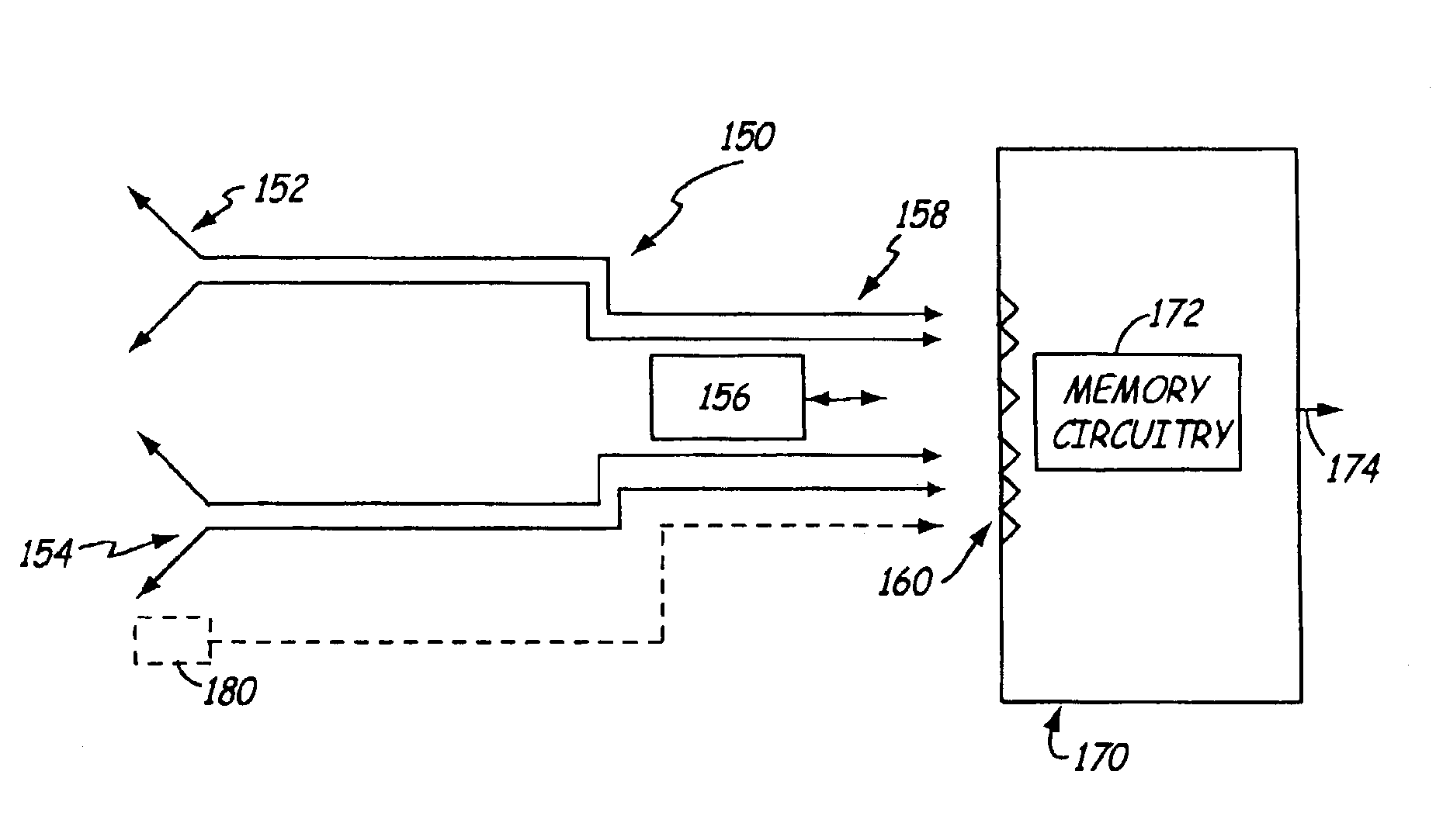
[0013]The present invention includes an electronic battery tester which communicates with a cable through which it is coupled to a battery. The tester can select a calibration value, suitable for the cable. The present invention also includes a cable for coupling a battery to a battery tester, wherein the cable includes a characteristic that is detectable by the tester.

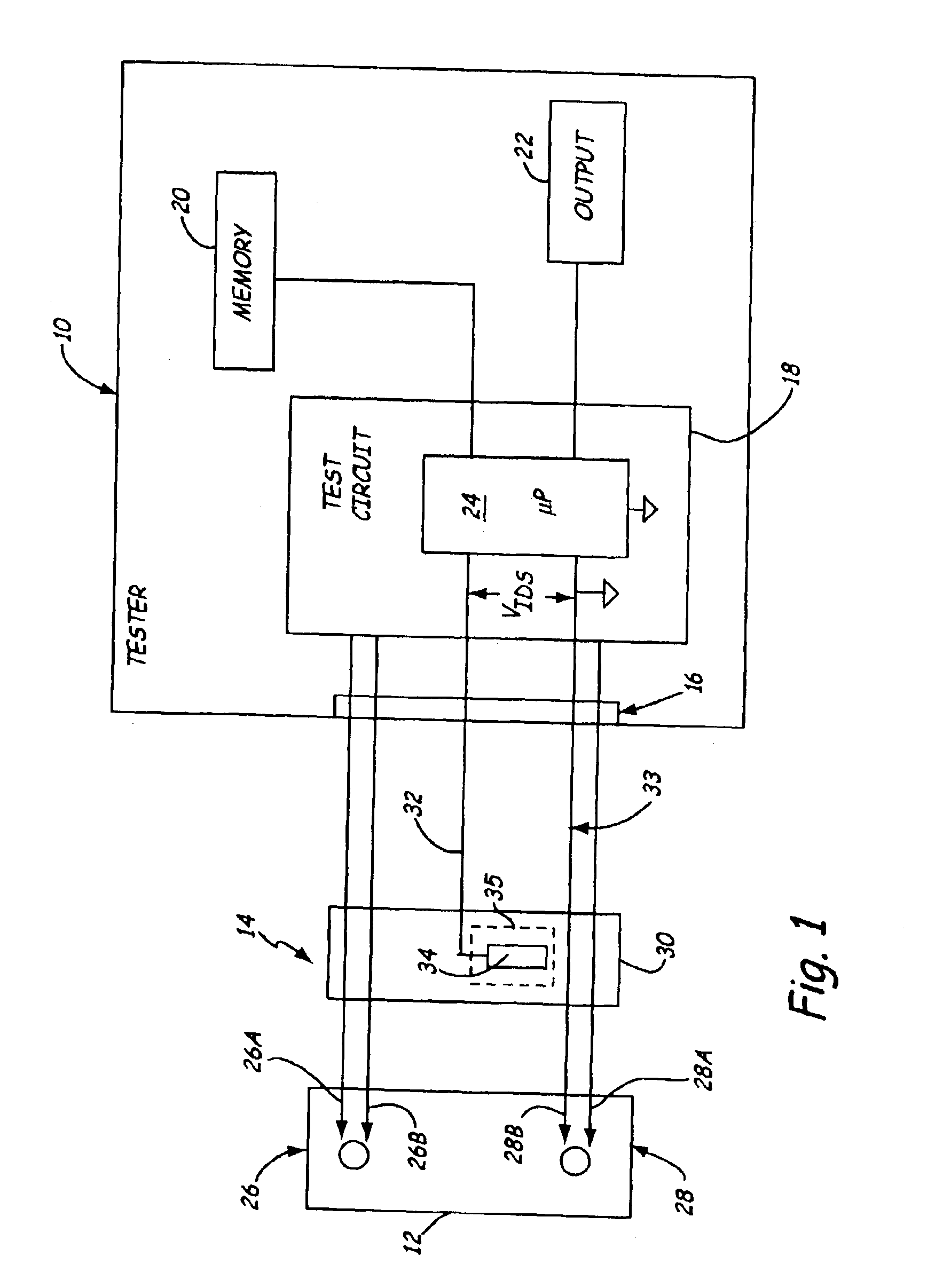
[0014]FIG. 1 is a very simplified block diagram of a battery tester 10 coupled to a battery 12 via a cable 14 in accordance with an illustrative embodiment of the present invention. The same reference numerals are used in the various figures to represent the same or similar elements. Note that FIG. 1 is a simplified block diagram of a specific type of battery tester. However, the present invention is applicable to any type of battery tester including those which do not use dynamic parameters. Other types of example testers include testers that conduct load tests, current based tests, voltage based tests, tests which a...


PUM

PropertyMeasurementUnit
voltage potentialaaaaaaaaaa
total voltageaaaaaaaaaa
electrical conductorsaaaaaaaaaa

Abstract

A cable for use with an electronic battery tester includes first and second electrical connections configured to couple to terminals of a battery. A memory is configured to store digital data. Electrical terminals are configured to couple the cable to the electronic battery tester.

Description

[0001]The present application is a Continuation-In-Part of and claims priority of U.S. patent application Ser. No. 10 / 396,550, filed Mar. 25, 2003, the content of which is hereby incorporated by reference in its entirety.BACKGROUND OF THE INVENTION[0002]The present invention relates to testing of storage batteries. More specifically, the present invention relates to an electronic battery tester capable of detecting the type of cable to which it is connected.[0003]Storage batteries, such as lead acid storage batteries of the type used in the automotive industry, have existed for many years. However, understanding the nature of such storage batteries, how such storage batteries operate and how to accurately test such batteries has been an ongoing endeavor and has proved quite difficult. Storage batteries consist of a plurality of individual storage cells electrically connected in series. Typically each cell has a voltage potential of about 2.1 volts. By connecting the cells in series,...

Claims


Application Information

Patent Timeline
Patent Type & Authority Patents(United States)
IPC IPC(8): G01R31/36
CPCG01R31/3648G01R31/3627G01R31/385
Inventor BERTNESS, KEVIN I.JEZIORCZAK, KRZYSZTOF
Owner MIDTRONICS
Why Eureka
Try Eureka