Lacing system

a lacing system and lacing technology, applied in the direction of fastenings, shoelace fastenings, footwear, etc., can solve the problems of current lacing systems, inability to maintain tension, and inability to provide snug fit of sneaker, so as to improve the safety, speed and safety of locking tapes, and improve the stability of skis. , the effect of improving the stability

Inactive Publication Date: 2005-09-13
FREED ANNA B
View PDF21 Cites 61 Cited by
  • Summary
  • Abstract
  • Description
  • Claims
  • Application Information

AI Technical Summary

Benefits of technology

[0007]Accordingly, it is an object of the present invention to provide a lacing system which is easy to apply to a shoe, inexpensive, and easy to manufacture, strong, durable, versatile, reliable, and easy for the user to operate.
[0008]It is further an object of the present invention to provide for a lacing system which can easily be placed on shoes by a shoe manufacturer with little or no modification to the shoe.
[0009]It is another object of the present invention that it be independent of the shoe and be able to be purchased as an after market item to be put on the shoe entirely by the consumer. Thus, giving the user the benefit of installing the lacing system of the present invention on almost any of his laced shoes and also giving him the option of using the (matching) laces that came with the shoes.

Problems solved by technology

Of course, some users will not bother with tightening the laces at each eyelet pair, and, in this situation, the sneaker does not provide as snug of a fit.
This is time consuming, cumbersome, and requires that the user to have the know-how and dexterity to tie bow knots.
Additionally, current art lacing systems have other disadvantages such as they do not maintain their tension and are not safe because the bow knots often become undone.
Instead, the lace traverses back and forth and from top to bottom, and thus, (since the lace segments do not criss-cross in the opening (or slit), the shoe does not provide adequate support for the users foot.
These types of segments, which are not guided by the eyelets on the sides of the opening, are not safe, and further weaken the lacing for the boot.

Method used


Image

  • Lacing system
  • Lacing system
  • Lacing system

Examples


Embodiment Construction

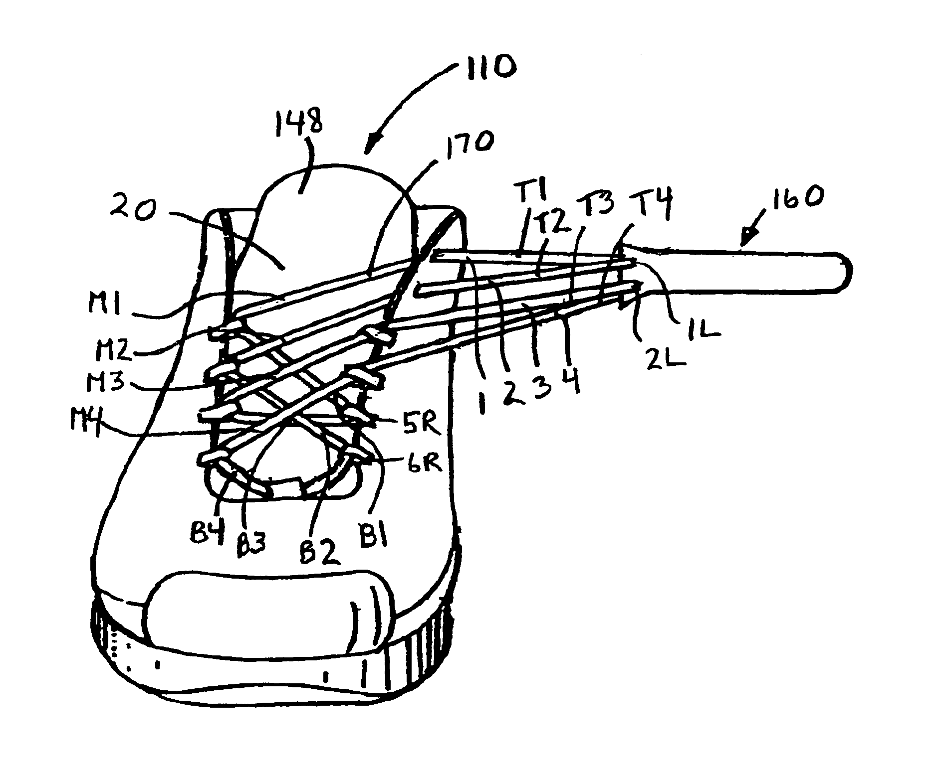
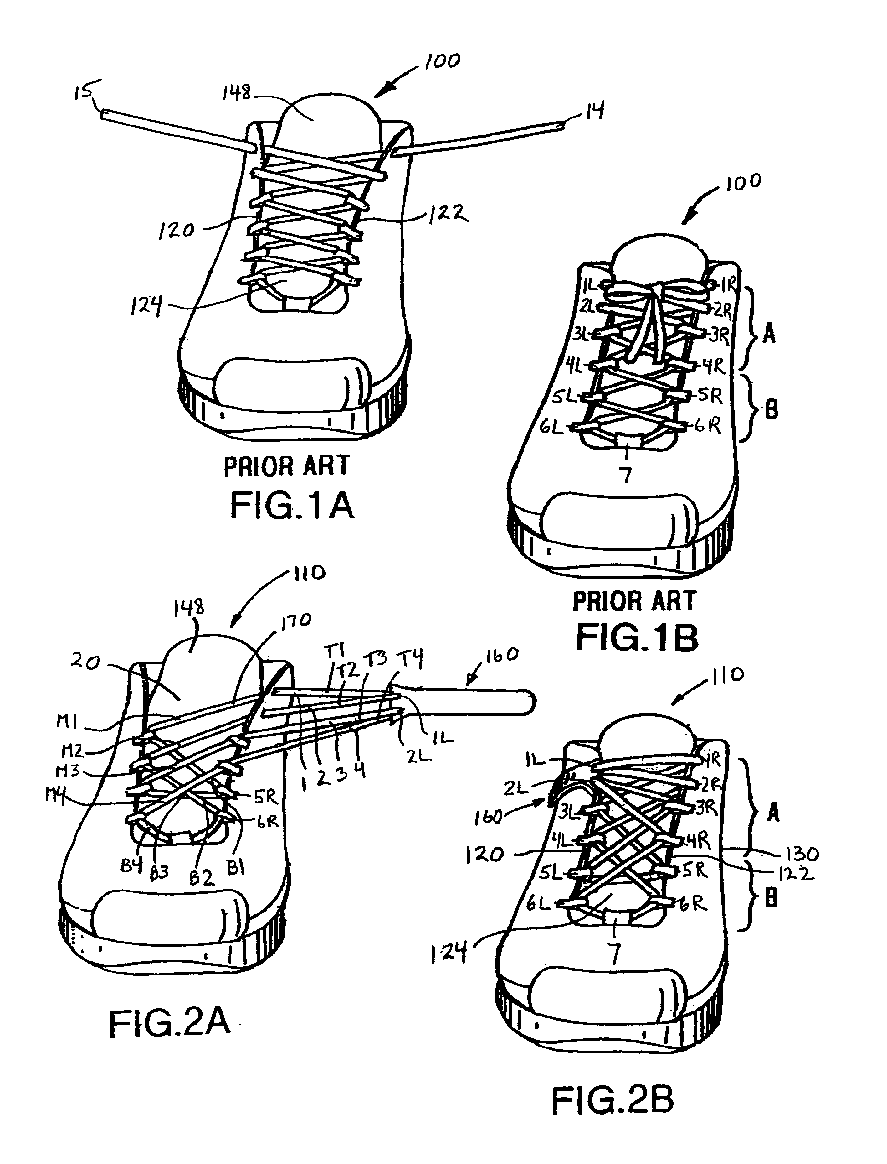
[0071]FIGS. 1A-B illustrate a conventionally laced sneaker 100, untied and tied respectively. The same number of eyelets are on either side 120, 122 of the adjustable opening 124. There are four pairs of eyelets over the instep (R=right, L=left) 3R,3L; 4R,4L; 5R,5L; 6R,6L There are two pairs of eyelets near the ankle 1R,1L; 2R,2L, which are placed there for additional support.

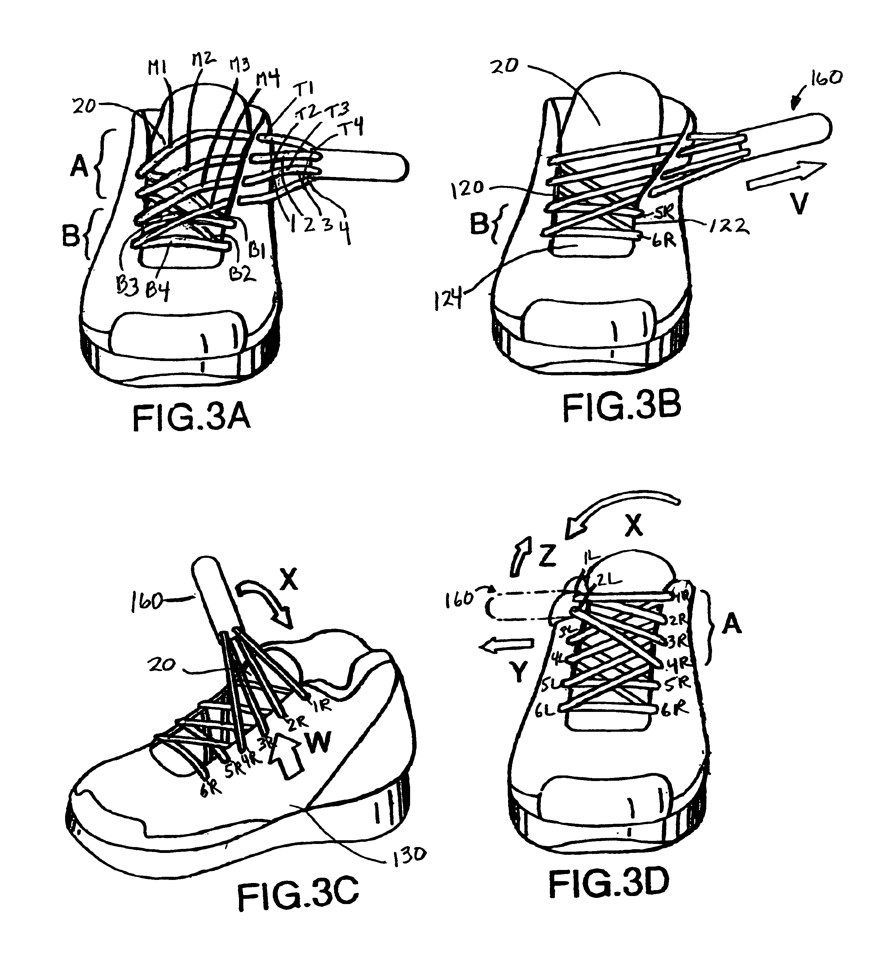
[0072]For the sake of brevity in the drawing illustrations, only the right sneaker 110 of the present invention is shown and discussed throughout this disclosure, however, one skilled in the art will readily recognize that the lacing system can be easily incorporated into a left sneaker (and other articles of footwear such as sandals, boots, skates, and slippers etc.). Two (2) basic embodiments are disclosed. The embodiments of the present invention with one (1) movable fastener are illustrated in FIGS. 2A-4F, 6A-61,8A and those with two (2) movable fasteners are illustrated FIGS. 7A-7H,8B-C. The eyelets could ...


PUM


Abstract

A lacing system having a lace loop that forms multiple segments that extend from a strap and criss-cross each other in an adjustable opening. The lace is threaded through eyelets of a sneaker, in such a manner that, a single arcuate pull on the strap(s), causes the multiple lace segments to move through the eyelets of the sneaker opening in unison, so that the entire length of the opening contracts simultaneously. This pull also lifts the entire arch area, thus providing better support. The lace segments converge at the strap(s), near the ankle, thus providing better support at the ankle. Additional lace segments could be disposed above the arch to provide better arch support. A strap or fastening member may attach to the sneaker by either a ratchet buckle, clasp, hook, snap, clamp, or locking tape such as hook-and-loop. The sneaker opens to its' maximum width, automatically when the user steps out.

Description

[0001]This is a Continuation-In-Part application of U.S. application Ser. No. 10 / 098,218 filed Mar. 14, 2002, now abandoned the disclosure of which is hereby fully incorporated by reference, which is a Continuation-In-Part application of international application # PCT / US01 / 28664 filed Sep. 14, 2001, the disclosure of which is hereby fully incorporated by reference, which entered the U.S. National stage as application Ser. No. 10 / 089,633 filed Mar. 28, 2002. This application is related to Provisional Patent Application Ser. No. 60 / 355,287 filed Feb. 6, 2002. The prior art of U.S. application Ser. No. 10 / 098,218 filed Mar. 14, 2002, now abandoned is included in this application.BACKGROUND OF THE INVENTION[0002]1. Field of Invention[0003]The present invention relates to the manner in which laces traverse the adjustable opening of sneakers for fastening. More generally, this invention relates to a lacing system which, in addition to fastening shoes, can be used to fasten articles of ma...

Claims


Application Information

Patent Timeline
Patent Type & Authority Patents(United States)
IPC IPC(8): A43C11/00A43C7/04A43C7/00
CPCA43C1/003A43C7/04A43C11/008Y10T24/3703Y10T24/37
Inventor FREED, ANNA B
Owner FREED ANNA B
Why Eureka
Try Eureka