Method and apparatus for generating steam for a cooking device

a technology of cooking device and steam generator, which is applied in the direction of steam generation using mechanical energy, drum steam boiler, flash steam boiler, etc., can solve the problems of high energy and cost outlay, limited first volume part, and large demand for steam generator size, so as to simplify the structure, avoid rotatably implemented leads, and simplify the effect of installation and conta

Inactive Publication Date: 2005-11-01
RATIONAL AG
View PDF18 Cites 13 Cited by
  • Summary
  • Abstract
  • Description
  • Claims
  • Application Information

AI Technical Summary

Benefits of technology

The technical effect of this patent is reducing production and maintenance expenses while improving the usage duration of a product. This is achieved through simplifying the installation process and eliminating complex structures associated with traditional designs.

Problems solved by technology

The technical problem addressed in this patent is how to generate steam efficiently without requiring large amounts of space and causing issues related to scaling up the production process. Current methods require significant investments in equipment and have limitations in terms of achieving consistently high levels of steam quality. In addition, there may be challenges associated with maintaining optimal performance over time due to the buildup of minerals found in tap water.

Method used


Image

  • Method and apparatus for generating steam for a cooking device
  • Method and apparatus for generating steam for a cooking device
  • Method and apparatus for generating steam for a cooking device

Examples


Embodiment Construction

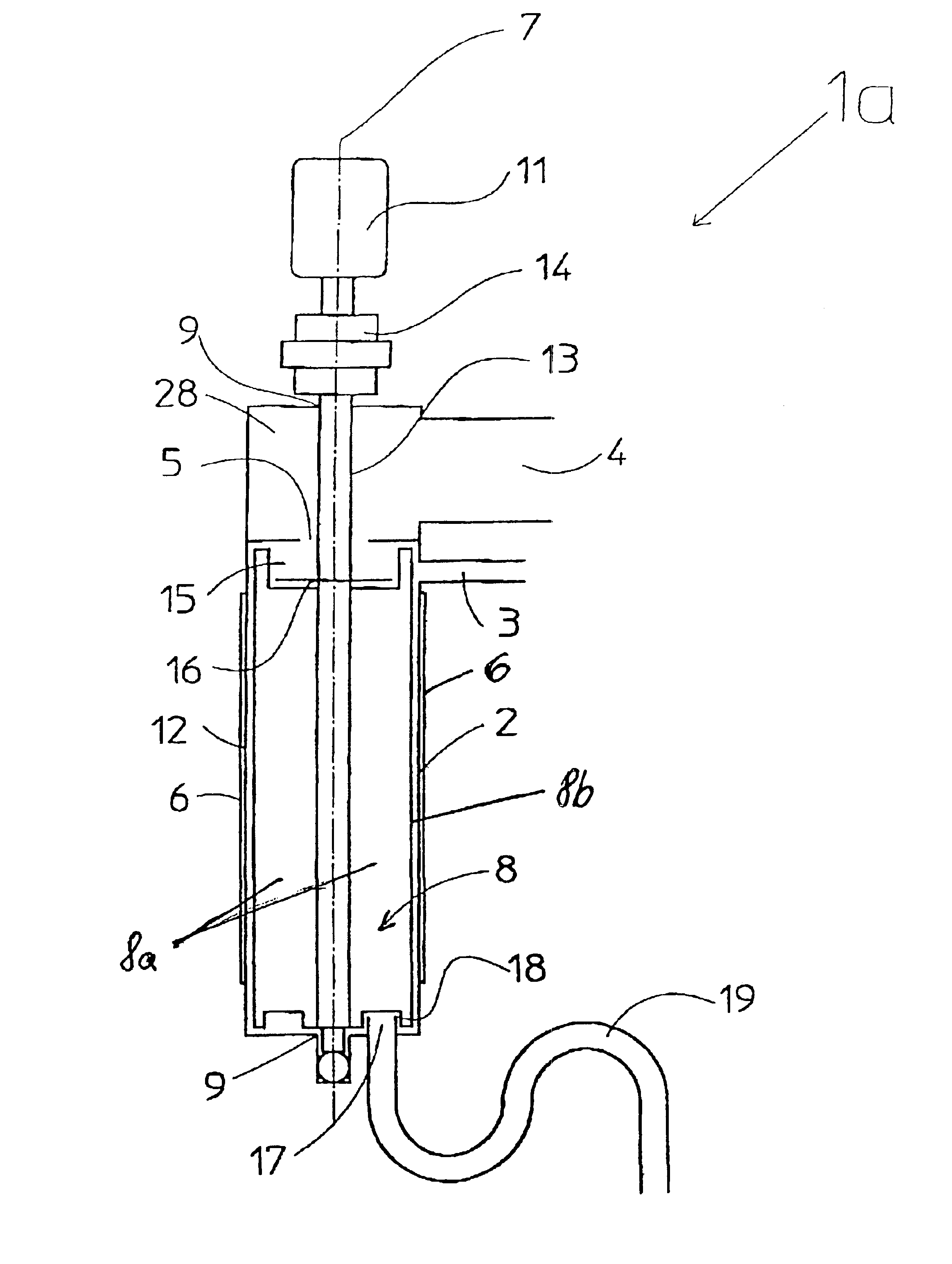
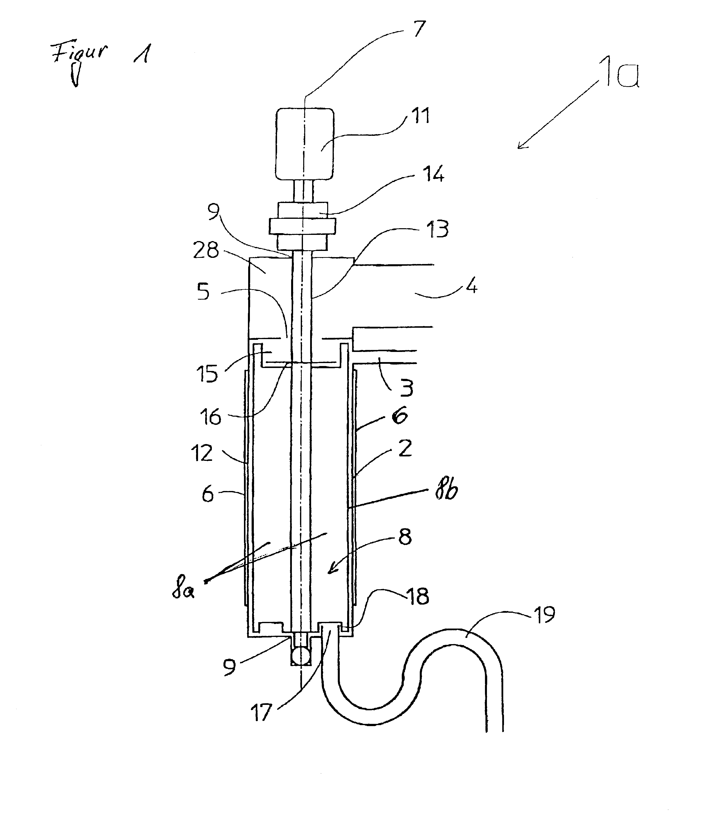
[0055]As can be derived from FIG. 1, an inventive steam generator 1a comprises a steam generating vessel in the form of a tubular boiler 2 with an admission or inlet in the form of a water inlet 3 and a steam outlet 4 at the upper end of the boiler 2, a diaphragm 5, which diaphragm separates the boiler 2 from the steam outlet 4, for condensate and contaminant separation, heating elements 6 in the form of a thick-film heater surrounding the tubular boiler 2, and a rotor in the form of a paddle 8 rotatable around a rotational axis 7 that coincides with the longitudinal axis of the boiler 2. The paddle 8 is seated with two bearings 9 and is driven with a motor 11 via a clutch 14, which is intended to compensate for adjustment errors, and a shaft 13. The paddle 8 comprises two paddle halves 8a, which have respective long paddle sides or edges 8b neighboring the wall surface 12 of the boiler 2, a recess 15 in the region of the diaphragm 5 and an impact disk 16 in order to generate a pote...


PUM


Abstract

A method and steam generator includes a steam generator container having a heated wall surface, an inlet for a liquid and an outlet for removing the vaporized liquid or steam, a rotor, which is mounted for rotation in the container and causes a rotational flow of the liquid outwardly against the heated wall to cause vaporization. During rotation of the rotor, outer edges of the blades of the rotor contact the wall surface to either abrade or wipe deposits, such as lime, from the wall surface.

Description


Claims


Application Information

Patent Timeline
Owner RATIONAL AG
Why Eureka
Try Eureka