Nestable and/or liftable rack

Inactive Publication Date: 2005-12-13
M & E MFG
View PDF46 Cites 19 Cited by
  • Summary
  • Abstract
  • Description
  • Claims
  • Application Information

AI Technical Summary

Benefits of technology

[0012]A still further object of the invention is to provide a rack which can be factory assembled, and shipped cost-effecti

Problems solved by technology

Known racks are expensive to manufacture, unsuited for various applications, require lots of storage space, are expensive to transport owing to their box-like, non-nestable

Method used


Image

  • Nestable and/or liftable rack
  • Nestable and/or liftable rack
  • Nestable and/or liftable rack

Examples


Embodiment Construction

FIGS. 1–2

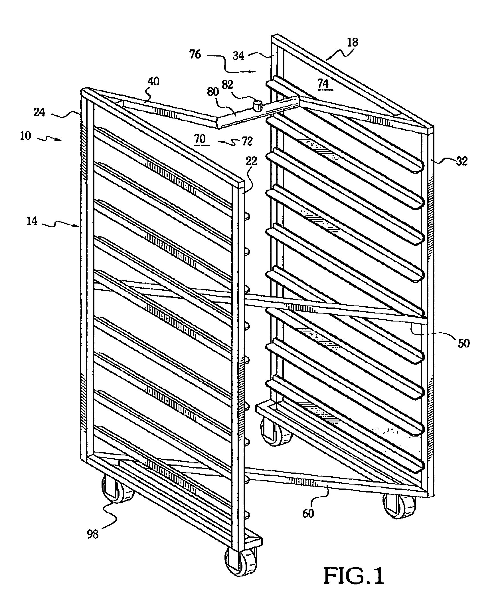
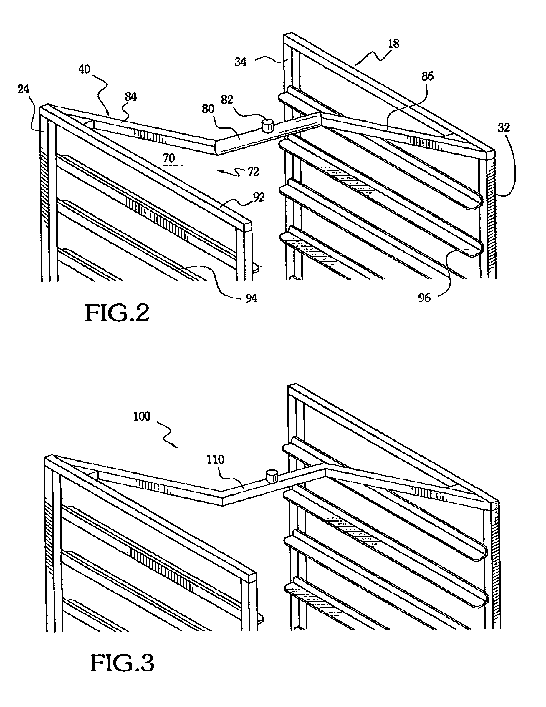
[0045]FIGS. 1–2 illustrate a first preferred embodiment of the invention.

[0046]A rack 10 includes a left upright frame 14 and a spaced apart right upright frame 18.

[0047]Left frame 14 includes a left front post 22 and a left rear post 24. Likewise, right upright frame 18 includes a right front post 32 and a right rear post 34.

[0048]An upper connector 40 connects left frame 14 to right frame 18. Typically, upper connector 40 may be made of square tubing, and bolted, or welded, to left and right frames 14, 18, respectively.

[0049]A middle connector 50 may be provided for added strength.

[0050]In a similar fashion, a lower connector 60 may be provided at the bottom of rack 10.

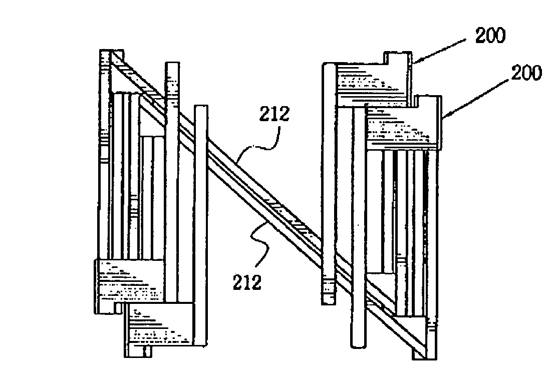
[0051]A left passage 70 having a mouth 72 is defined at an upper portion of rack 10 for receiving at least one of left rear posts 24 and right front posts 32 of another rack 10, when rack 10 and another rack 10 are nested together. That is, when two racks 10 have been pushed together so as to reduce the amo...


PUM


Abstract

Rack includes a left upright frame, a right upright frame, and a connector extending between and joining the left and right frames. The connector defines at least one (1) passage extending along the left upright frame, for example, so that another rack may be nested within a volume defined by the rack for reducing storage space requirements. The rack may have its connector oriented so that the rack has a substantially Z-shaped frame, when viewed from above. Wheels may be provided to ease movement of the rack, and a lifting element may be provided on an upper portion of the rack for use with institutional and industrial lifting mechanisms.

Description

CROSS-REFERENCE TO RELATED APPLICATIONS[0001]This application is a continuation-in-part of application Ser. No. 08 / 847,483, filed Apr. 25, 1997 now U.S. Pat. No. 6,419,098, which claims the priority of provisional application No. 60 / 034,853, filed Jan. 28, 1997, entitled “Nestable and / or Liftable Rack”, and which claims the priority of provisional application No. 60 / 017,343, entitled “Nesting Oven Racks Equipped with Brackets for Lifting the Rack”, filed Apr. 26, 1996, and each of which is incorporated herein by reference.[0002]This application relates to Applicant's co-pending Application Ser. No. 10 / 183,565, filed Jun. 28, 2002, entitled “V-SHAPED NESTABLE TRAY RACK”, which is incorporated herein by reference.FIELD OF THE INVENTION[0003]This invention relates to a rack.[0004]More particularly, this invention relates to a rack suited for holding and supporting objects.[0005]Specifically, the invention relates to a rack configured for nesting with other like racks.[0006]Still furthe...

Claims


Application Information

Patent Timeline
IPC IPC(8): A47B47/02A47F5/13B62B3/18
CPCA47B47/021A47F5/137B62B3/002B62B3/188B62B3/006
Inventor HALL, DONALD M.
Owner M & E MFG
Why Eureka
Try Eureka