Encoding and sensing of syringe information

a technology of information and syringe, applied in the field of encoding and sensing of information or configuration, can solve the problems of limited syringe configurations, automatic detection of limited number of automatic detection switches, and failure of moving mechanisms, so as to reduce manufacturing costs, prevent interference with magnetic resonance imaging equipment, and increase reliability

Inactive Publication Date: 2006-03-28
BAYER HEALTHCARE LLC
View PDF28 Cites 187 Cited by
  • Summary
  • Abstract
  • Description
  • Claims
  • Application Information

AI Technical Summary

Benefits of technology

[0010]In one embodiment, the electromagnetic energy is light energy and the length of material can, for example, have a refractive index greater than the refractive index of an adjacent environment such that light energy can be internally reflected in the material along its length. Internal reflectance assists in efficiently propagating light energy through the length of the material. Indicators suitable for use with light energy include, for example, angled surfaces in the syringe wall adapted to refract and / or reflect light energy outside of the syringe wall.
[0018]The encoding schemes of the present invention provide a reliable manner of encoding information of, for example, syringe configuration. Mechanically movable mechanisms are not required, resulting in increased reliability as compared to many prior encoding schemes. Moreover, the syringe encoders of the present invention are readily formed integrally with, for example, a syringe or a syringe adapter, resulting in less costly manufacture than many prior encoding mechanisms.

Problems solved by technology

Constraints of mechanical and electrical design, however, limit the number of such automatic detection switches.
Indeed, only limited syringe configurations are automatically detected with present systems.
Additionally, failure of moving mechanisms is also a problem.
Moreover, certain electrical and mechanical encoding systems can significantly increase manufacturing costs of a syringe and / or injector.
Bar code systems, however, suffer from some of the same problems as the electromechanical systems discussed above.

Method used


Image

  • Encoding and sensing of syringe information
  • Encoding and sensing of syringe information
  • Encoding and sensing of syringe information

Examples


Embodiment Construction

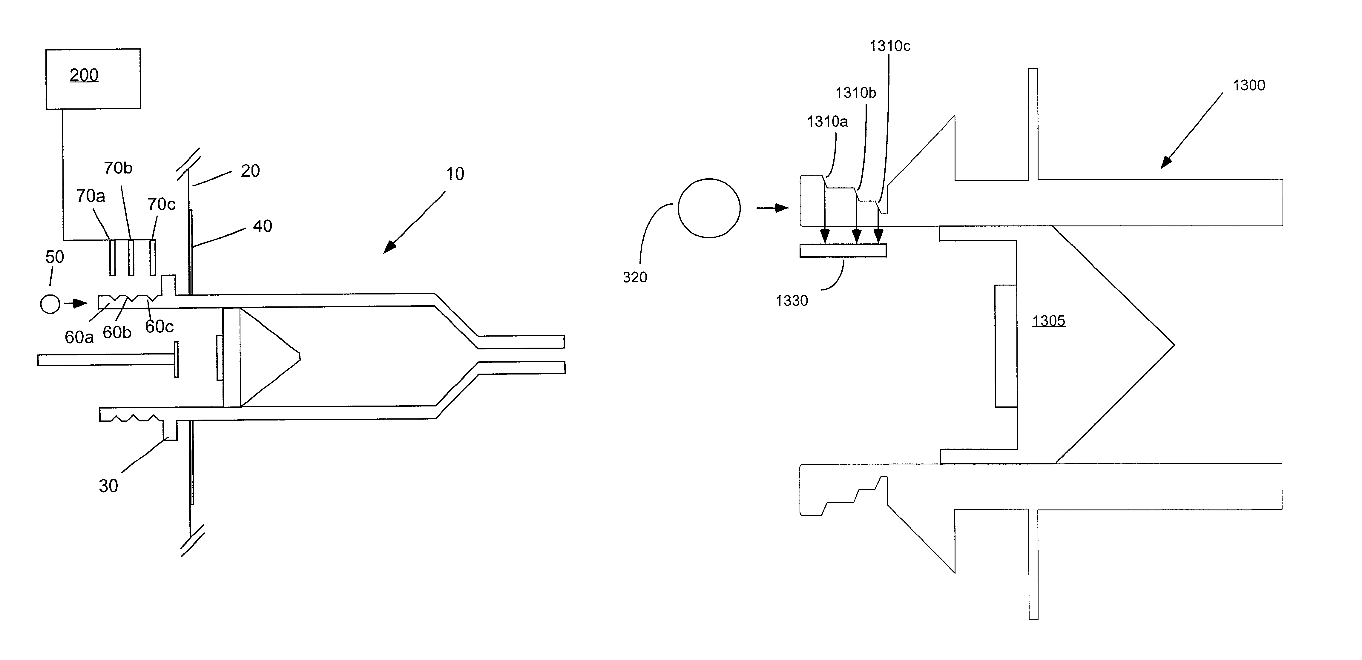
[0052]The encoders, encoding systems and encoding methods of the present invention are particular useful in encoding information of configuration for syringes and other pumping mechanisms used in medical injection procedures. Several representative embodiments of the present invention in which light energy is used in connection with syringe encoders are discussed below.

[0053]In the case that light energy is used in the present invention, one can, for example, take advantage of the properties of light refraction / reflection at an interface between two different media to assist in efficiently propagating light through the length of the media having the higher refractive index. These different media can, for example, be a translucent or transparent syringe wall and the air surrounding the syringe wall.

[0054]The refraction of light at an interface between two dielectric media is governed by Snell's Law as follows:

n1 sin θ1=n2 sin θ2

wherein n1 and n2 are the refractive indices of each die...


PUM


Abstract

A syringe for use with a powered injector to inject a fluid into a patient that includes a length of material adapted to transmit or propagate electromagnetic energy therethrough. The length of material includes at least a first indicator positioned along the length of material. The first indicator is adapted to interact with at least a portion of the energy being propagated through the length of material in a manner that is detectable. The presence (or absence) of the first indicator provides or corresponds to information about the syringe configuration. The indicator(s) of the present invention can, for example, provide information about syringe configuration by the number and / or position thereof. A plurality or set of such syringes can be provided, with the configuration of each such syringe being represented by the presence or absence of indicator(s) of that syringe.

Description

FIELD OF THE INVENTION[0001]The present invention relates to encoding and sensing of information or configuration, and, especially, to syringes and syringe encoders having encoding of information relevant to medical injection procedure, to injector systems including syringe encoding and to methods of encoding and sensing syringe information.BACKGROUND OF THE INVENTION[0002]Critical parameters of an injection procedure are determined by a number of variables, including, for example, syringe diameter, syringe length, syringe material and fluid composition / concentration. Among the affected injection procedure parameters are fluid volume delivered, flow rate, fluid pressure, and limits of injector piston travel. In current injector systems, syringe size is generally determined either (1) manually by action of an operator who enters the syringe size or type into the injector software, or (2) automatically by means of switches on the injector head which are mechanically coupled to raised ...

Claims


Application Information

Patent Timeline
Patent Type & Authority Patents(United States)
IPC IPC(8): A61M1/00A61M3/00A61M5/00G01R33/28A61B5/055A61M5/145
CPCA61M5/1452G01D5/12A61M5/3129A61M2205/6036A61M2005/3125A61M2205/6063
Inventor COWAN, KEVIN P.IDDON, BARRYYANNIELLO, MICHAEL J.BROSOVICH, JOHN A.HIRSCHMAN, ALAN D.
Owner BAYER HEALTHCARE LLC
Why Eureka
Try Eureka