Apparatus and method for suspending a stator core of an electric generator

a technology of stator core and suspension structure, which is applied in the direction of dynamo-electric machines, supports/encloses/casings, magnetic circuit shapes/forms/construction, etc., can solve the problems of serious vibration and load problems, material fatigue and damage of supporting structure parts, and easy vibration and noise, so as to reduce noise and fatigue, the effect of simple construction

Inactive Publication Date: 2006-05-16
ALSTOM TECH LTD
View PDF12 Cites 7 Cited by
  • Summary
  • Abstract
  • Description
  • Claims
  • Application Information

AI Technical Summary

Benefits of technology

[0012]The object of the present invention is to reduce or eliminate the problems outlined above. This object and others are obtained by providing an apparatus and method for suspending a stator core in an electric generator upon a foundation, which is simple in construction and reliable in withstanding static, dynamic and shock loads, also minimising noise and fatigue. Natural modes of vibration are excited in the stator core during operation, including a known second vibration mode with four circumferentially distributed loops and four nodes being displaced 45 degrees from the loops, and a known third vibration mode with four loops and four nodes displaced 45 degrees in relation to the loops and nodes of the second vibration mode.

Problems solved by technology

Cyclical forces are then exerted on the stator and its supporting structure as the rotor rotates, giving rise to vibrations and noise.
Excessive vibrations in combination with a high static load may also lead to material fatigue and damages of the supporting structure parts.
In particular, such vibration and load problems are serious and difficult to combat in the case of very large and heavy machines, such as electric generators in power plants.
Moreover, sudden shock loads may occur in electric generators due to short circuit conditions or synchronising faults.
In the worst case, the supporting structure may be damaged and accidents may happen.
The stator core is thus subjected to radial forces and counter-forces due to the magnetic field as the rotor rotates, which result in an oscillating elastic deformation of the core mainly in a radial direction.
These radial oscillations tend to be transmitted over the supporting structure to the foundation upon which the generator rests, imposing vibrations thereto, which are undesirable for reasons mentioned above.
A relatively stiff structure provides a solid static load support, but is less successful in isolating vibrations, and vice versa.
Moreover, the entire deflection movement and vibration energy of a stator core is taken up by deformation of the spring elements, which puts high demands on the spring elements to withstand wear and fatigue.

Method used


Image

  • Apparatus and method for suspending a stator core of an electric generator
  • Apparatus and method for suspending a stator core of an electric generator
  • Apparatus and method for suspending a stator core of an electric generator

Examples


Embodiment Construction

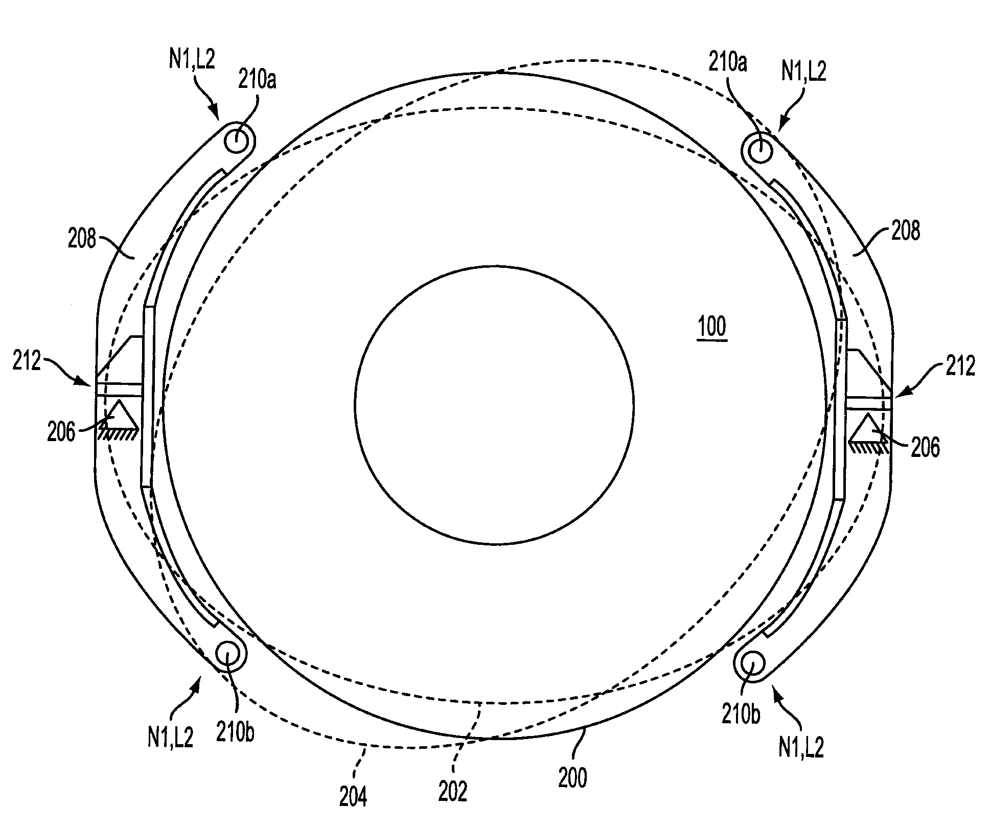
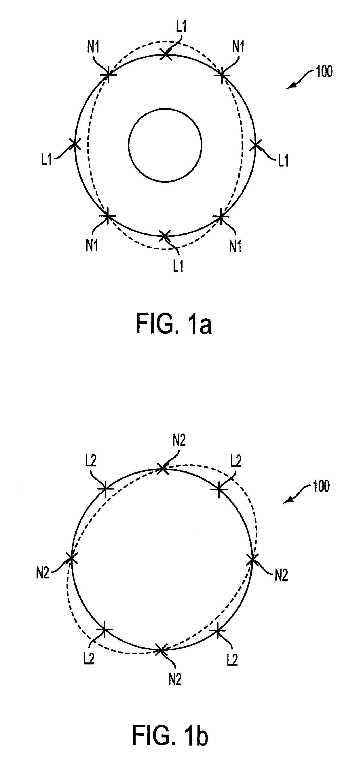
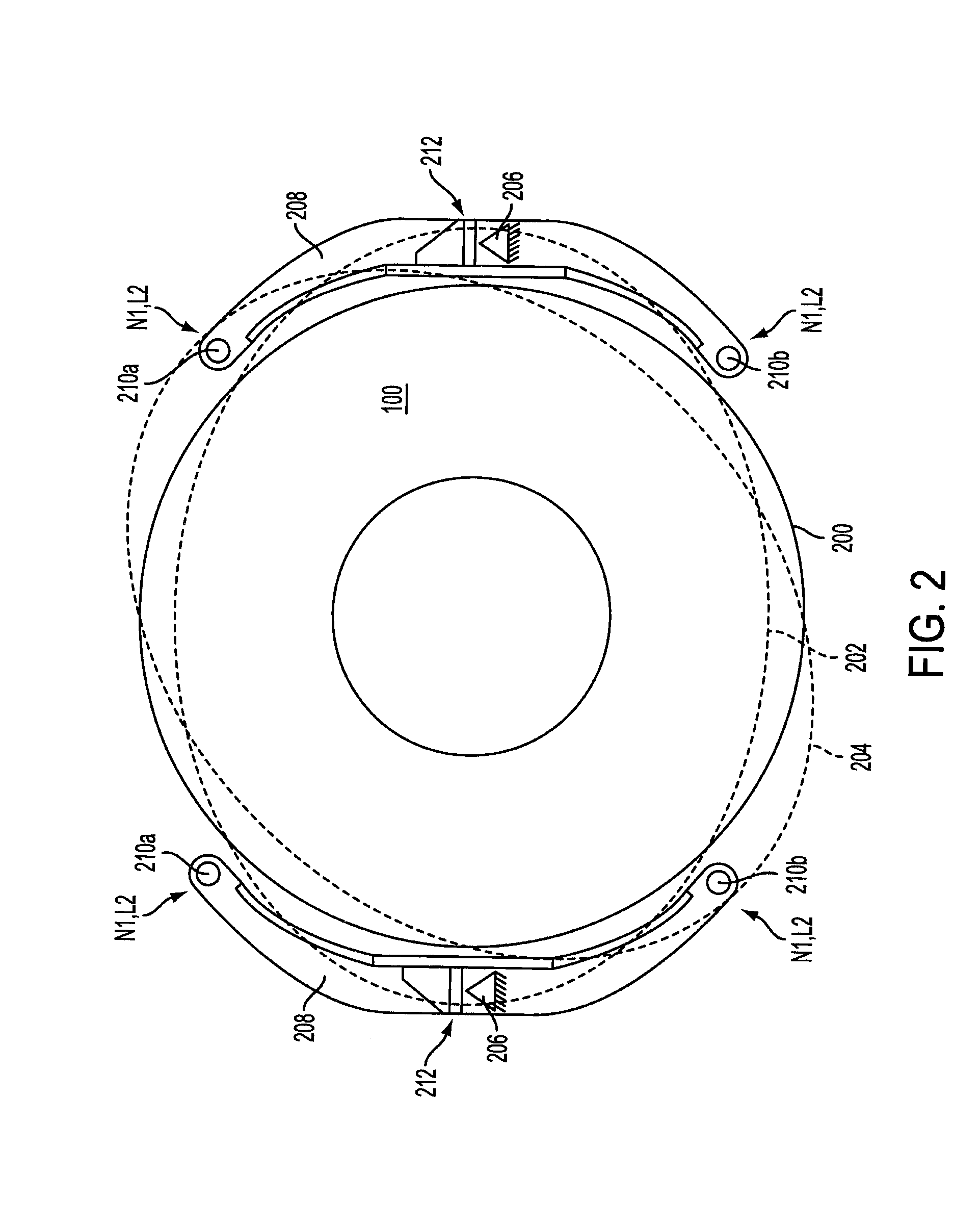
[0019]The present invention takes advantage of the natural modes of vibration typically occurring in the stator core of an electric generator, due to dynamic forces on the stator core imposed by a generated magnetic field, when using a two-pole rotor. In many electric generators, the natural frequency of the vibration modes in the stator core unfortunately happens to be approximately twice the rotation speed of the rotor being commonly used in order to optimise the electric performance.

[0020]The resonance pattern of a ring-shaped or tube-shaped stator core includes two superposed modes of vibration in the form of radial oscillations, which are illustrated in FIGS. 1a and 1b, respectively. In the figures, a continuous circle represents the outer periphery of the stator core when undeformed, and a dashed ellipse represents the mode shape, i.e. the outer periphery of the stator core when deformed according to the respective vibration mode.

[0021]It is generally known that a tube-shaped ...


PUM


Abstract

An apparatus and method for suspending a stator core (100) in an electric generator upon a foundation (206), where two natural modes of vibration, including known second and third modes, are excited in the core, each mode having four loops and four nodes displaced 45 degrees between the second and third modes. A non-rigid connection (212) connects a yoke to the foundation, and two connection members connect the yoke to the stator core at opposite sides of the non-rigid connection. The two connection points (210a,b) are located at adjacent loops of one of the second and third vibration modes. By this arrangement, radial deflections of the stator core at the respective connection points are transferred into a rocking movement of the yoke around the non-rigid connection. Thereby, vibrations transferred to the foundation are considerably reduced during operation.

Description

[0001]This application claims priority under 35 U.S.C. § 119 to Swedish patent application number 0200929-8, filed on Mar. 26, 2002, the entirety of which is incorporated by reference herein.TECHNICAL FIELD[0002]The present invention relates generally to an apparatus and method for vibration-free suspension of an electric generator. In particular, the invention relates to a suspension structure for suspending the stator core of the generator.BACKGROUND OF THE INVENTION AND PRIOR ART[0003]In electric generators, energy is transferred between a mechanical state and an electrical state by means of a generated magnetic field and windings in a rotating rotor and a stationary stator, in a well-known manner. Cyclical forces are then exerted on the stator and its supporting structure as the rotor rotates, giving rise to vibrations and noise. Excessive vibrations in combination with a high static load may also lead to material fatigue and damages of the supporting structure parts. In particu...

Claims


Application Information

Patent Timeline
Patent Type & Authority Patents(United States)
IPC IPC(8): H02K5/24H02K5/26
CPCH02K1/185
Inventor JONSON, LEIF
Owner ALSTOM TECH LTD
Why Eureka
Try Eureka