Snowmobile power steering system

a technology for power steering and snowmobiles, applied in the direction of steering devices, sledges, cycle equipments, etc., can solve the problems of limiting the positional freedom of mounting components on snowmobiles, slow response characteristics, etc., to reduce the force required for steering the snowmobile, limit the positional freedom of mounting components, and improve the effect of balance and performan

Active Publication Date: 2006-08-29
YAMAHA MOTOR CO LTD
View PDF13 Cites 40 Cited by
  • Summary
  • Abstract
  • Description
  • Claims
  • Application Information

AI Technical Summary

Benefits of technology

[0010]One aspect of the present invention includes the realization that the typical structures and arrangements of power steering devices as used on some vehicles presents problems with balance and performance when used on some snowmobiles. For example, if a power steering device is positioned on one side of the vehicle body, an offsetting weight is required on the opposite side of the vehicle body for balance. This can limit the positional freedom in mounting components on a snowmobile. Additionally, if a universal joint is provided as described above, play is typically present in the universal joint interposed between the input shaft and the steering shaft. Play in the universal joint delays the operation of the power steering device with respect to the steering force generated by turning the steering handlebar. Thus, although the force required for steering the snowmobile can be reduced by including a power steering device, the response characteristic may be slow.
[0011]Accordingly, in another aspect of the present invention, a snowmobile has a power steering device that makes it easy to balance weight in the transverse direction of the vehicle, without significantly reducing the response characteristic.
[0018]In another aspect, a pair of steering skis are provided in positions on both sides of an engine. The power steering device is located above and behind the engine. The engine can function as a shield to inhibit snow from adhering to the power steering device.

Problems solved by technology

This can limit the positional freedom in mounting components on a snowmobile.
Thus, although the force required for steering the snowmobile can be reduced by including a power steering device, the response characteristic may be slow.

Method used


Image

  • Snowmobile power steering system
  • Snowmobile power steering system
  • Snowmobile power steering system

Examples


Embodiment Construction

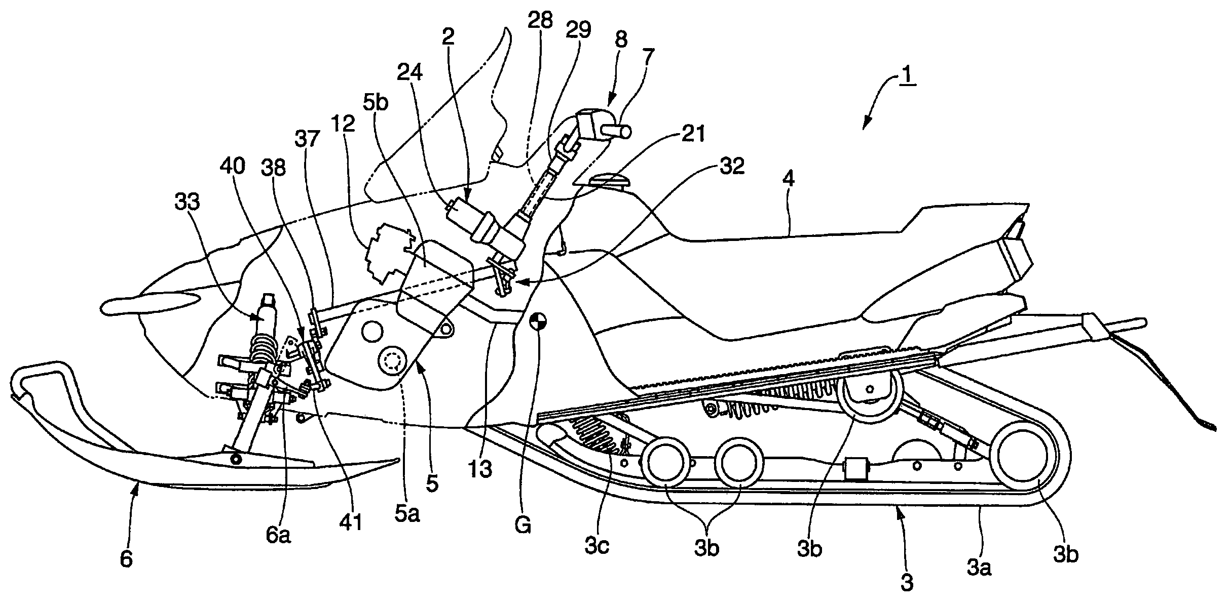
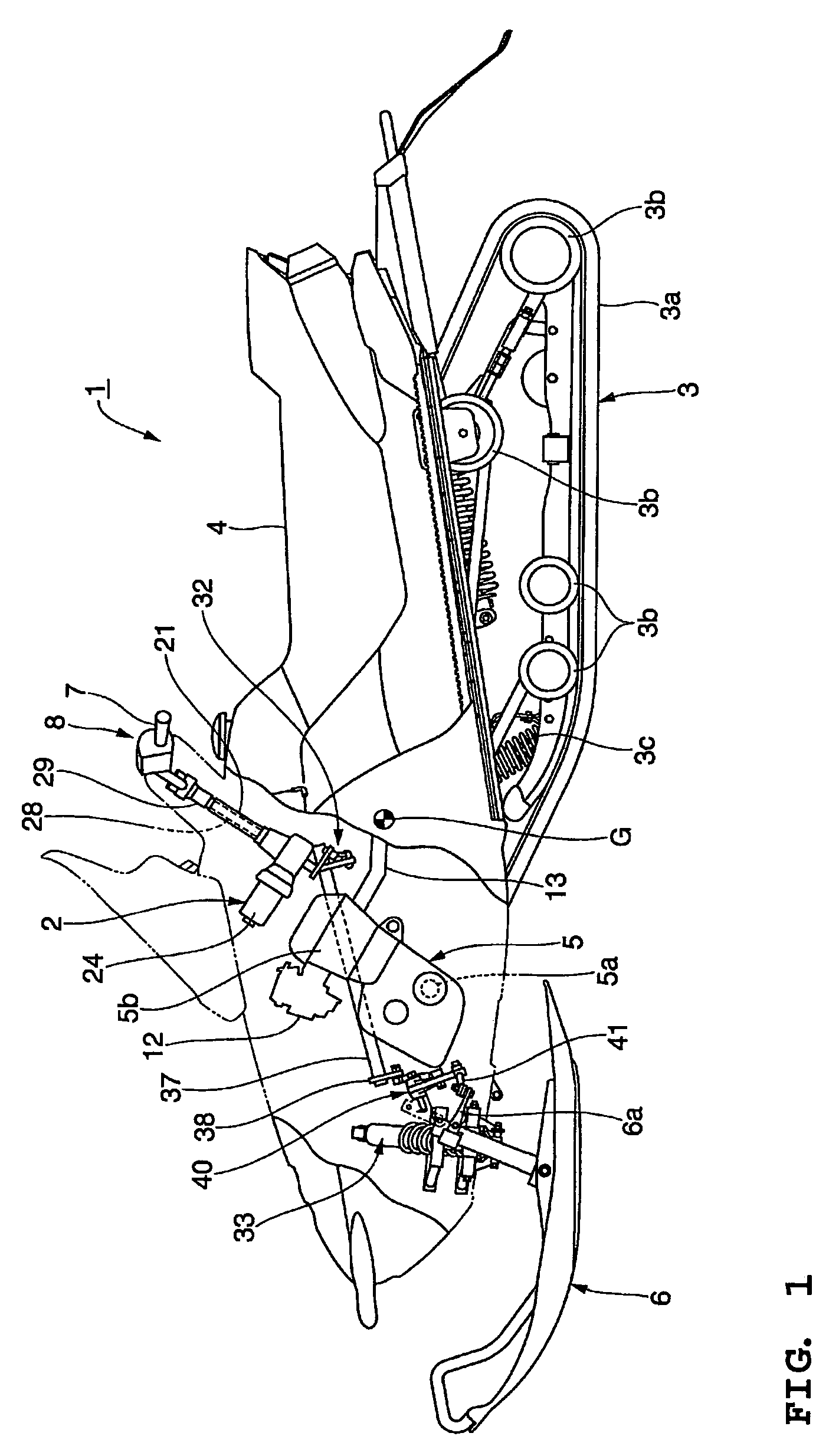
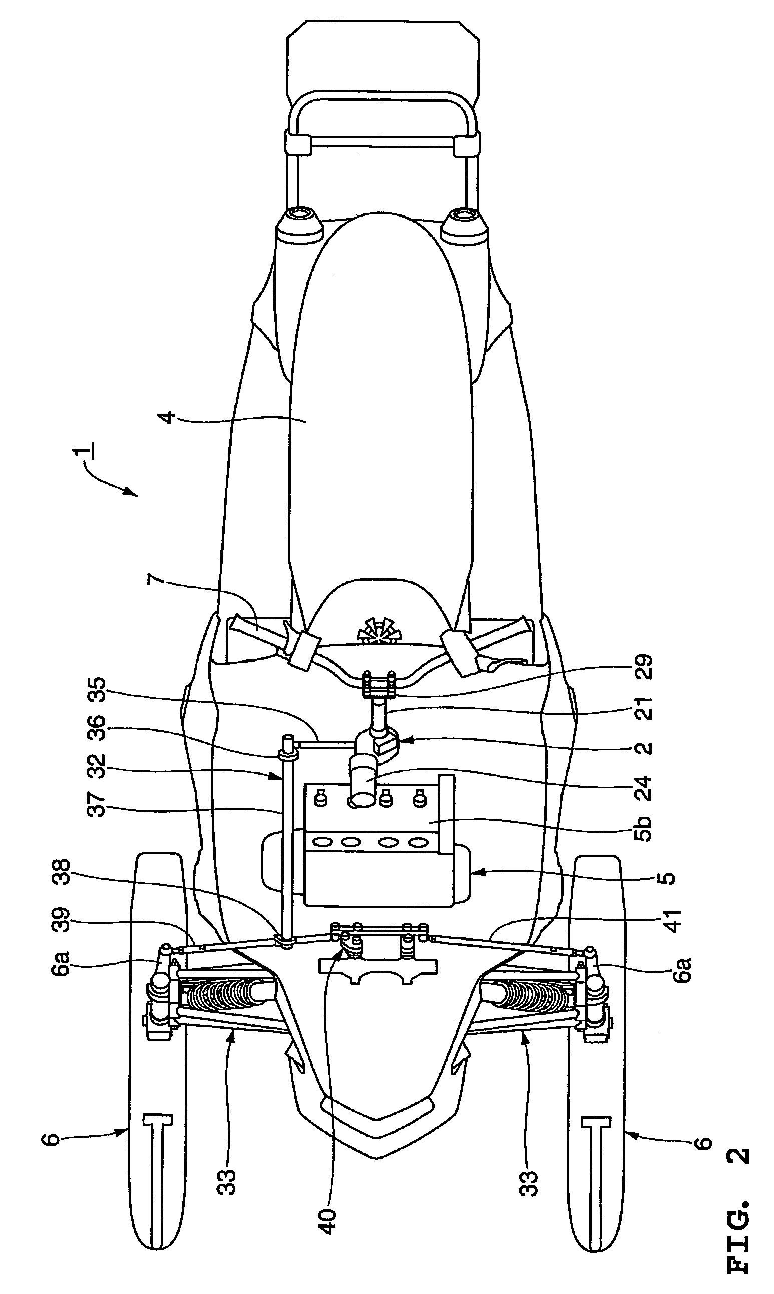
[0028]With reference now to FIG. 1, one embodiment of a snowmobile having certain features, aspects and advantages of the present invention will be described. The snowmobile, indicated generally by the reference numeral 1, is an environment for which many features, aspects and advantages of the present invention have been specially adapted. Nevertheless, certain features, aspects and advantages of the present invention can be used with other vehicles.

[0029]The snowmobile 1 generally comprises a frame assembly 9 (see FIG. 3) that carries a number of other components of the snowmobile 1. A forward body cover is disposed over a forward portion of the frame assembly 9. The forward body cover defines, in part, an engine compartment in which an engine 5 is mounted. The engine 5 will be described in greater detail below.

[0030]A windshield is disposed over a mid-portion of the body cover. The windshield provides some degree of protection for the riders from wind and other elements during op...


PUM


Abstract

A snowmobile comprises a frame assembly. An internal combustion engine is mounted to the frame assembly. A steering assembly is mounted to the frame assembly. The steering assembly comprises a steering shaft having a first portion and a second portion. The first portion of the steering shaft is coupled to a steering input mechanism. The second portion of the steering shaft is coupled to a power steering device. The power steering device is coupled to a steering linkage. The steering linkage is coupled to a steering ski.

Description

RELATED APPLICATIONS[0001]This application is based upon and claims priority to Japanese Patent Application No. 2003-206780, filed on Aug. 8, 2003, which is hereby incorporated by reference in its entirety.BACKGROUND OF THE INVENTION[0002]1. Field of the Invention[0003]The present invention generally relates to steering systems for vehicles. More specifically, the present invention relates to power steering systems for snowmobiles.[0004]2. Description of the Related Art[0005]With some snowmobiles, a rider straddles a seat and grips a steering handlebar provided in front of the seat. The steering handlebar typically is disposed in a position at an upper end of a steering shaft. The steering shaft usually is located centrally in a transverse direction of the vehicle. A lower end of the steering shaft is connected through a linkage mechanism to a pair of right and left steering skis. The steering shaft is supported for free rotation within a steering column. The steering column can be ...

Claims


Application Information

Patent Timeline
Patent Type & Authority Patents(United States)
IPC IPC(8): B62M27/02B62M29/00B62K21/00
CPCB62M27/02B62K21/00
Inventor MORIYAMA, TAKASHI
Owner YAMAHA MOTOR CO LTD
Why Eureka
Try Eureka