Fiber optic light bar

a fiber optic and light bar technology, applied in the field of light, can solve the problems of difficult control of the lighting of the room wherein the lamp is located, the lamp is not easily affixed to a generally vertical surface, and the tubular member is typically not flexible in the manner through which it is mounted, so as to achieve the effect of improving the light bar

Inactive Publication Date: 2006-09-19
ROY LAURIER
View PDF12 Cites 2 Cited by
  • Summary
  • Abstract
  • Description
  • Claims
  • Application Information

AI Technical Summary

Benefits of technology

[0015]Advantageously, the light bar is relatively light, relatively easy to assemble and relatively easy to manufacture. Also, the light bar creates flexibility in the way in which it is supported, which adds flexibility to the various uses of the light bar.

Problems solved by technology

Therefore, it is somewhat difficult to control the lighting of a room wherein the lamp is located.
Also, the lamp is not easily affixed to a generally vertical surface.
However, there is typically no flexibility in the manner through which a tubular member is mounted to a surface or supported by a base.
In addition, commercially available lights have a geometry that makes assembly of the light difficult.

Method used


Image

  • Fiber optic light bar
  • Fiber optic light bar
  • Fiber optic light bar

Examples


Embodiment Construction

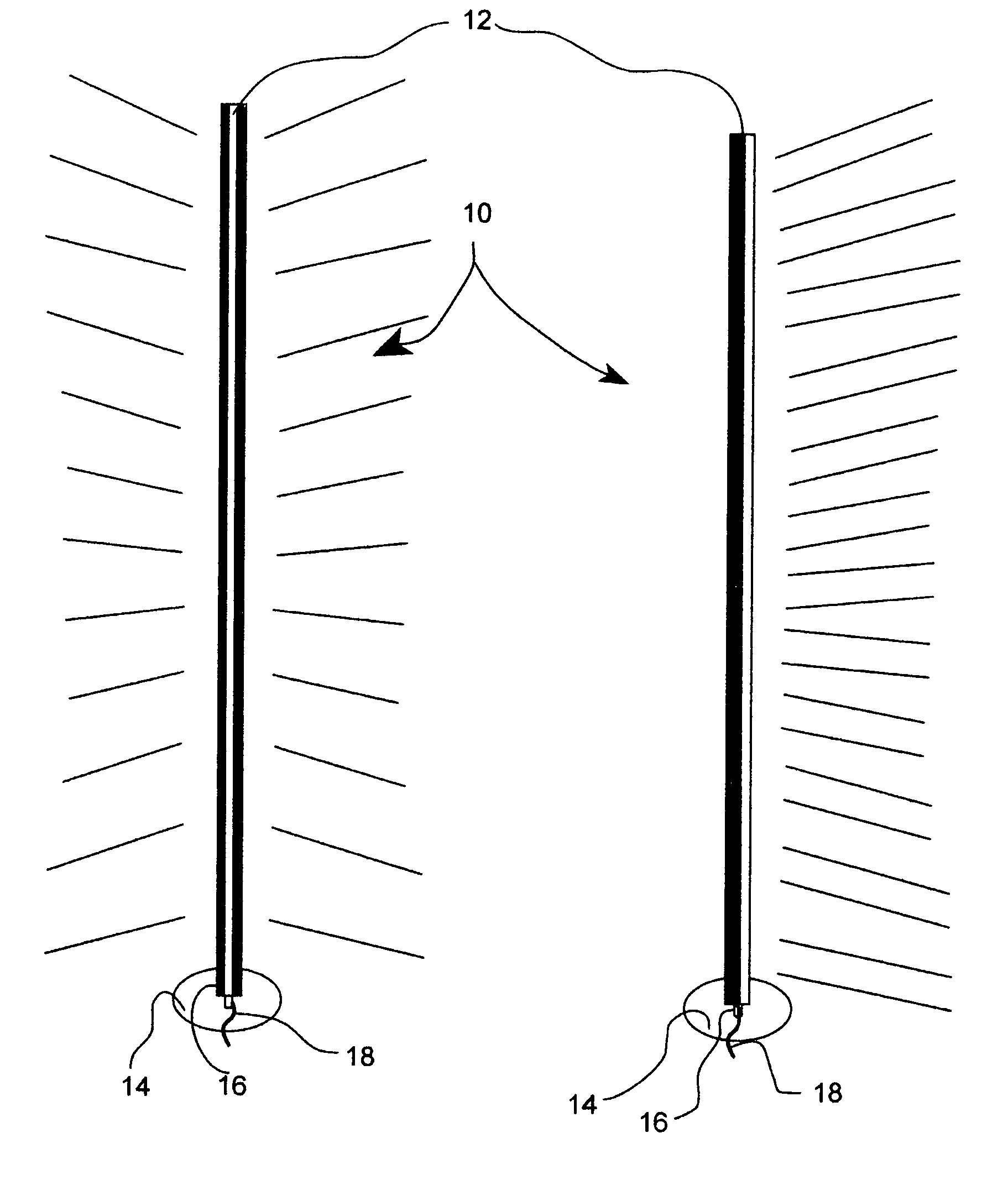
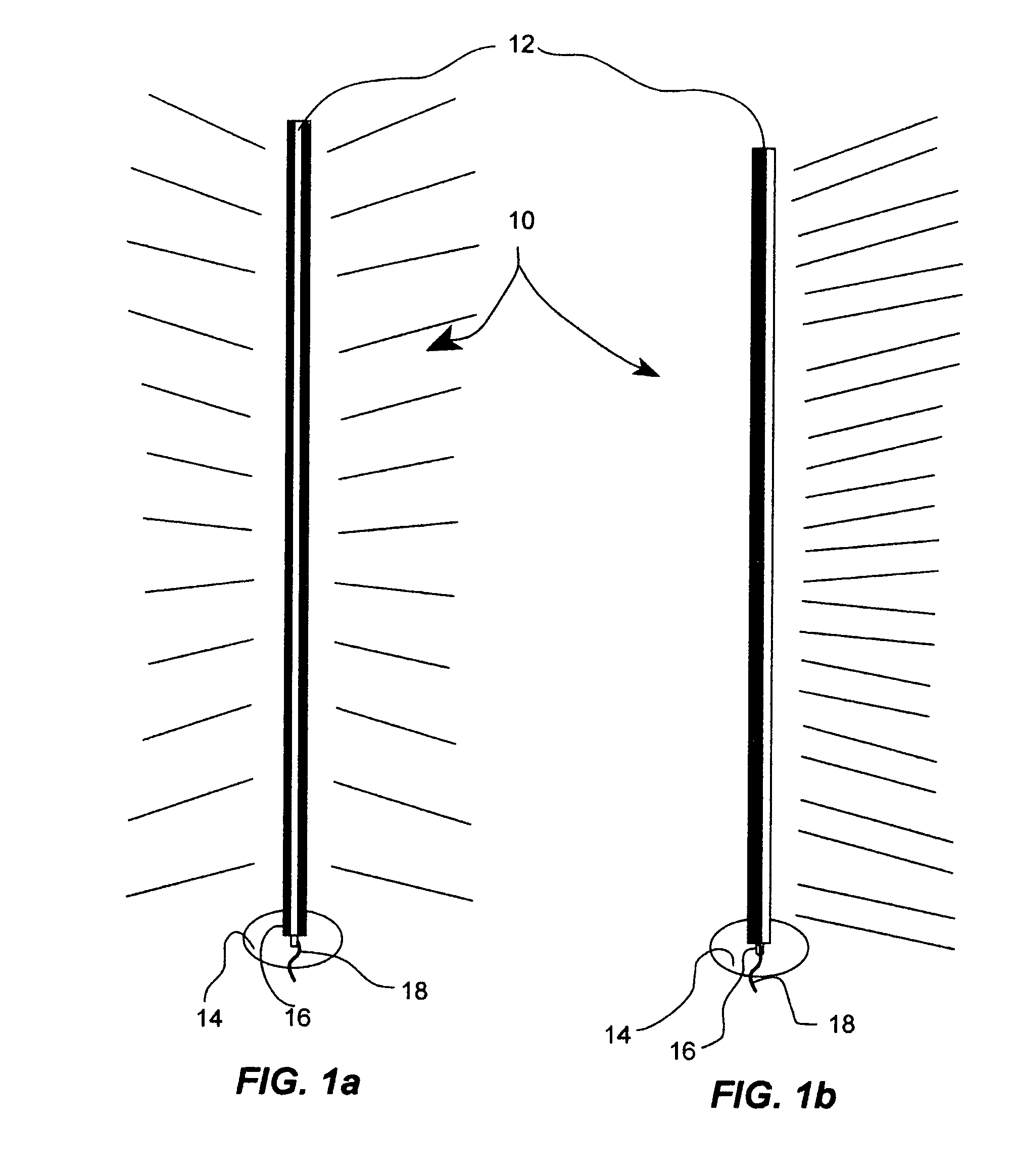
[0036]FIGS. 1A and 1B show a lamp 10 including a fiber optic light bar 12, a base 14 and a support tube 16. The support tube 16 is mounted to and substantially perpendicular to the base 14. The fiber optic light bar 12 is connected to the support tube 16. An optical fiber 18 is provided within the fiber optic light bar 12. A light source (not shown in the drawings) provides light to the optical fiber 18.

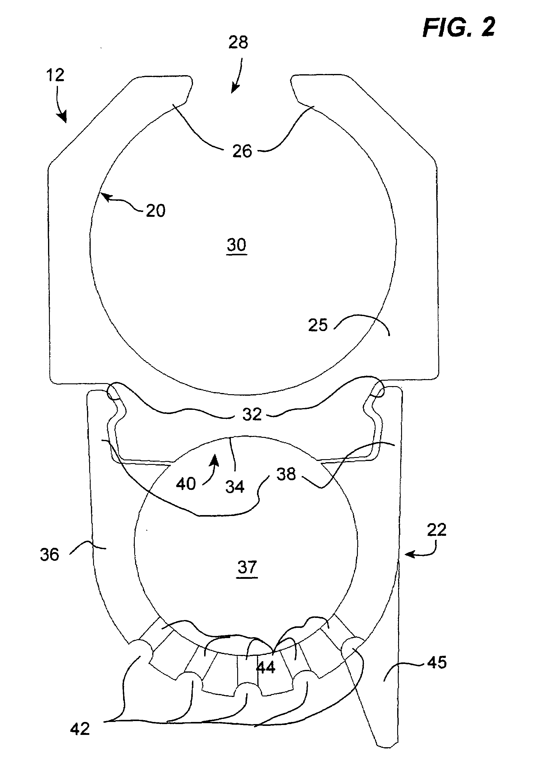
[0037]The optical fiber 18 is a multi-strand optical fiber. As described in more details hereinbelow, the fiber optic light bar 12 includes a plurality of holes 44 for receiving strands of the optical fiber 18 and through which emerges a ray of light 19. Therefore, when light is provided into the optical fiber 18, the lamp 10 provides illumination through the various strands optical fiber 18 exiting through the holes 44 of the fiber optic light bar 12.

[0038]In a specific embodiment of the invention, the fiber optic light bar 12 includes a substantially uniform cross section. This all...


PUM


Abstract

A light bar includes an optical fiber, a mounting member, and a fiber supporting member. The fiber supporting member is connected to the mounting member. The optical fiber is supported by the fiber supporting member.

Description

[0001]This application claims priority based on provisional application 60 / 575,830 filed Jun. 2, 2004FIELD OF THE INVENTION[0002]The present invention relates to lights. More specifically, the present invention is concerned with a fiber optic light bar.BACKGROUND OF THE INVENTION[0003]There are many types of lights using optical fiber that are commercially available. These lights are used both in home and commercial settings.[0004]One example of such a light is a lamp including a base and a multi-strand optical fiber. The optical fiber is inserted into the base and the strands of the optical fiber form a sphere above the base. In this lamp, light is emitted in all directions.[0005]In this type of lamp, there is no directionality to the light emitted. Therefore, it is somewhat difficult to control the lighting of a room wherein the lamp is located. Also, the lamp is not easily affixed to a generally vertical surface.[0006]Other examples of fiber optic lights include a tubular member ...

Claims


Application Information

Patent Timeline
Patent Type & Authority Patents(United States)
IPC IPC(8): G02B6/00A41F1/00F21V8/00F21V17/08F21V21/088F21V21/116G02B6/36H02G3/20H02G3/32
CPCF21V21/116H02G3/32H02G3/20G02B6/0006F21V21/088G02B6/3616
Inventor ROY, LAURIER
Owner ROY LAURIER
Why Eureka
Try Eureka