Shift register and display driving device comprising the same

a technology of display driving device and shift register, which is applied in the direction of instruments, computation using denominational number representation, pulse technique, etc., can solve the problems of difficult to construct a circuit that is operationally stable, long time is required to change the output signal to the low level, and inferior a-sitfts and p-sitfts, etc., to achieve the effect of stabilizing circuit operation and suppressing malfunction

Active Publication Date: 2007-05-08
CASIO COMPUTER CO LTD
View PDF3 Cites 42 Cited by
  • Summary
  • Abstract
  • Description
  • Claims
  • Application Information

AI Technical Summary

Benefits of technology

[0012]The present invention provides a shift register having the advantage of being able to suppress malfunctioning if the operating frequency of circuits is increased to some degree, thus stabilizing circuit operations in a display driving device comprising the shift register.
[0043]reducing a voltage level of the output signal in response to the application of the predetermined voltage to the second wiring.

Problems solved by technology

However, a-SiTFTs and p-SiTFTs are inferior, in operational characteristics, to monocrystal Si-based transistors conventionally used to construct the scan and signal drivers.
It is thus difficult to construct a circuit that is operationally stable and that exhibits a sufficient performance, using a-SiTFTs or p-SiTFTs.
Consequently, after the application of the reset signal, a long time is required to change the output signal to the low level.
That is, a fall in the output signal is relatively delayed.
However, such an increase in clock frequency may delay the fall in the output signal from each shift circuit, thus making circuit operations unstable.
This may lead to malfunctioning.

Method used


Image

  • Shift register and display driving device comprising the same
  • Shift register and display driving device comprising the same
  • Shift register and display driving device comprising the same

Examples


Embodiment Construction

[0074]On the basis of an embodiment shown in the drawings, description will be given of a shift register, a method for driving the shift register, and a display driving device comprising the shift register in accordance with the present invention.

[0075]In the description of the present embodiment, an example of a display driving device is a scan driver for a liquid crystal display apparatus to which a shift register in accordance with the present invention is applied. However, the present invention is not limited to this but is applicable to, for example, a signal driver.

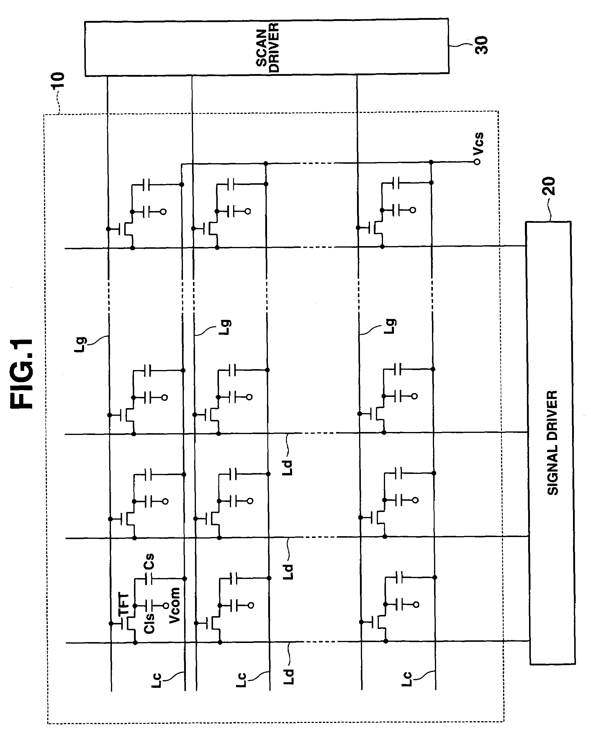
[0076]FIG. 1 is a diagram showing the configuration of an essential part of a liquid crystal display apparatus in accordance with the present invention.

[0077]The liquid crystal display apparatus comprises a display panel 10, a signal driver 20, a scan driver 30, and the like. The display panel 10 comprises a plurality of signal lines Ld disposed across the column, a plurality of scan lines Lg disposed across the row...


PUM


Abstract

A shift circuit of a shift register includes an output terminal, an input terminal, a reset terminal. A voltage is applied to a first wiring in response to the output signal from the preceding stage shift circuit to the input terminal and in accordance with the predetermined voltage to the first wiring, outputting an externally applied signal to the output terminal. A voltage level of the first wiring is reduced in response to the output signal to the reset terminal by the preceding stage shift circuit. The voltage is applied to the second wiring in response to a change in the level of the voltage applied to the first wiring. The voltage is applied to a second wiring in response to the output signal to the reset terminal by the preceding stage shift circuit. A voltage level of the output signal is reduced in response to the predetermined voltage to the second wiring.

Description

CROSS-REFERENCE TO RELATED APPLICATIONS[0001]This application is based upon and claims the benefit of priority from prior Japanese Patent Application No. 2004-358443, filed Dec. 10, 2004, the entire contents of which are incorporated herein by reference.BACKGROUND OF THE INVENTION[0002]1. Field of the Invention[0003]The present invention relates to a shift register having a plurality of stages including of a plurality of cascaded shift circuits and a method for driving the shift register, as well as a display driving device comprising the shift register to drive a display panel.[0004]2. Description of the Related Art[0005]Amorphous silicon thin-film transistors TFT (referred to as “a-SiTFTs” below) and polysilicon thin-film transistors (referred to as “p-SiTFTs” below) are used as, for example, display driving elements constituting pixels in a liquid crystal display panel.[0006]The liquid crystal display panel has a plurality of scan lines and a plurality of signal lines. The scan l...

Claims


Application Information

Patent Timeline
Patent Type & Authority Patents(United States)
IPC IPC(8): G09G3/36G11C19/00
CPCG11C19/00G11C19/28G09G3/3688G02F1/133G09G3/20G09G3/36H03K19/00
Inventor MOROSAWA, KATSUHIKOYAMAMOTO, TAKUMI
Owner CASIO COMPUTER CO LTD
Why Eureka
Try Eureka