Autostereoscopic display apparatus

a display apparatus and autostereoscopic technology, applied in the field of display apparatuses, can solve the problems of reducing the display brightness, reducing the display quality, so as to improve the display brightness, eliminate aberrations, and improve the display

Inactive Publication Date: 2007-06-05
EASTMAN KODAK CO
View PDF13 Cites 8 Cited by
  • Summary
  • Abstract
  • Description
  • Claims
  • Application Information

AI Technical Summary

Benefits of technology

[0053]It is an advantage of the invention that a beamsplitter is not required for forming the curved intermediate image. This improves display brightness and eliminates aberrations that can be induced by such a beamsplitter.
[0054]It is an advantage of the present invention that it enables the use of a larger imaging display than previous solutions, relaxing Lagrange invariant constraints on available luminance.
[0055]It is a further advantage of the present invention that it provides a large viewing pupil.
[0056]It is a further advantage of the present invention that it provides a compact autostereoscopic display system providing a virtual image. The apparatus of the present invention overcomes constraints on the placement and size of projection apparatus for left- and right-eye images by folding the image path at an optimal location. Thus, conventional projection systems having relatively large lenses can be used for forming stereoscopic images.
[0057]It is yet a further advantage of the present invention that it provides options to highly spherical lenses, such as ball lenses and ball lens segments, using an alternate approach to image-forming optics that generate curved images.

Problems solved by technology

As a group, these conventional approaches have been adapted for autostereoscopic displays, but allow only a narrow field of view and provide limited brightness and poor contrast.
Time-based multiplexing introduces the inherent problem of image flicker.
), may provide an increased number of views, but does not compensate for these inherent drawbacks.
As a further disadvantage, each of the imaging technologies described in the Pastoor et al. article present the viewer with a real image, rather than with a virtual image, a distinction described in more detail subsequently.
However, the optical system disclosed in this article is subject to field curvature constraints, limiting its field of view.
Notably, the system described in the Hopf article provides a virtual image; however, due to substantial field curvature, the total field of view of such a system is limited to less than about 15 degrees.
While such a narrow field of view may be acceptable for videoconferencing applications, this level of performance would not be useful for a desktop display system.
It is recognized in the optical arts that each of these requirements, by itself, can be difficult to achieve.
It is well known that conflict between depth cues associated with vergence and accommodation can adversely impact the viewing experience.
It is known that there can be a temporary degradation of a viewer's depth perception when the viewer is exposed for a period of time to mismatched depth cues for vergence and accommodation.
There are also other basic optical limitations for immersion systems that must be addressed with any type of optical projection that provides a wide field of view.
An important limitation is imposed by the Lagrange invariant.
An invariant that applies throughout the optical system, the Lagrange invariant can be a limitation when using, as an image generator, a relatively small spatial light modulator or similar pixel array which operate over a relatively small numerical aperture, since the Lagrange value associated with the device is small.
At the same time, however, the use of a diffusive surface effectively reduces overall brightness, introduces some level of graininess to the image, and limits the achievable contrast.
Although there is considerable interest in the enhanced display quality that true autostereoscopic virtual imaging affords, there remain a number of hurdles to widespread commercialization of compact, autostereoscopic displays suitable for desktop applications.

Method used


Image

  • Autostereoscopic display apparatus
  • Autostereoscopic display apparatus
  • Autostereoscopic display apparatus

Examples


system embodiment

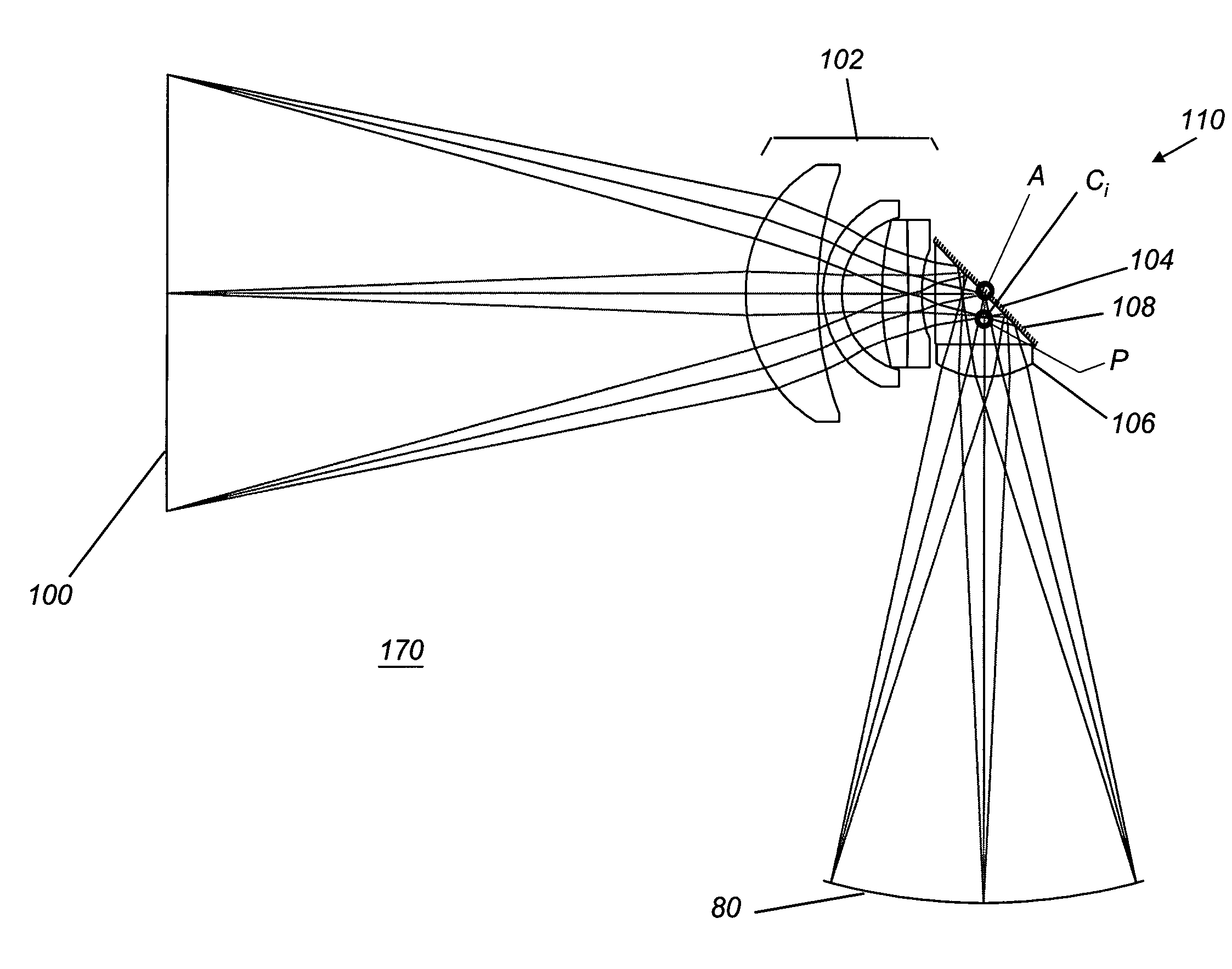
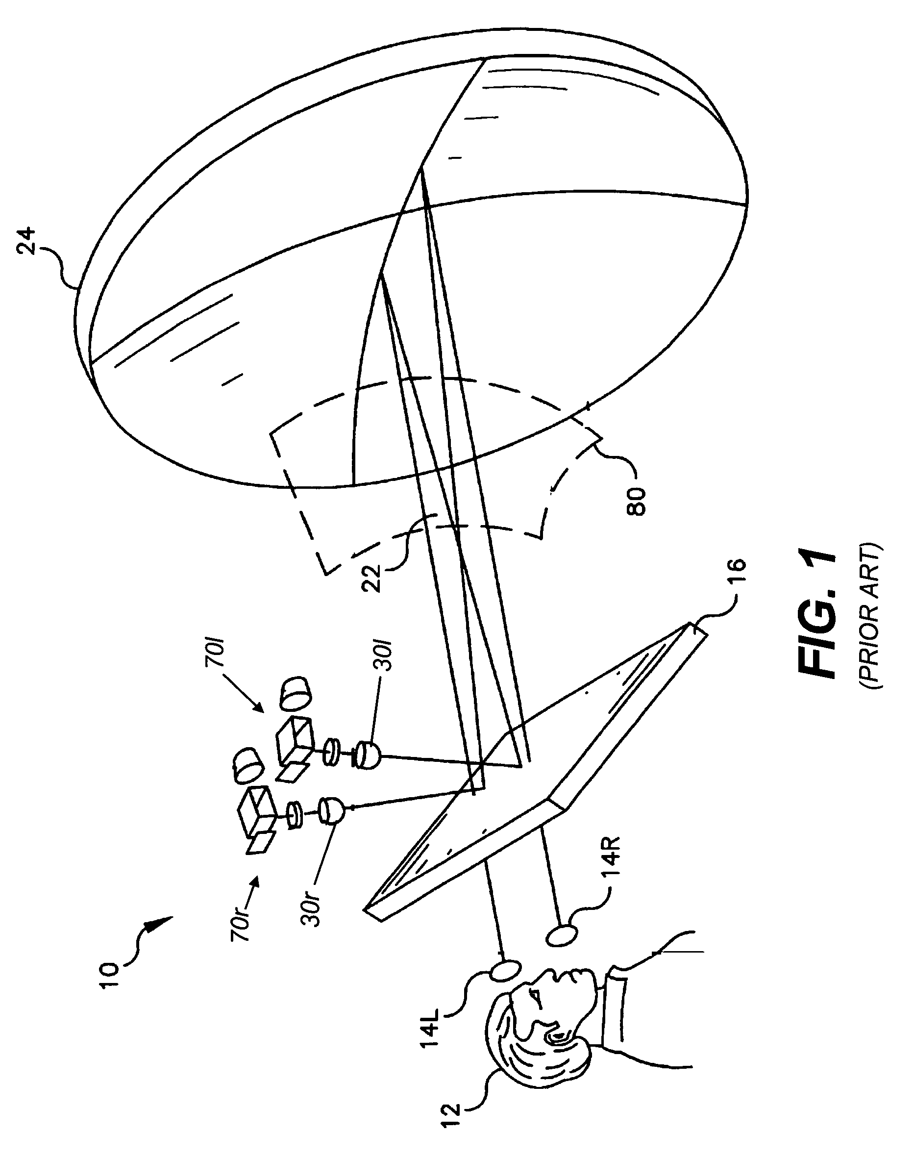
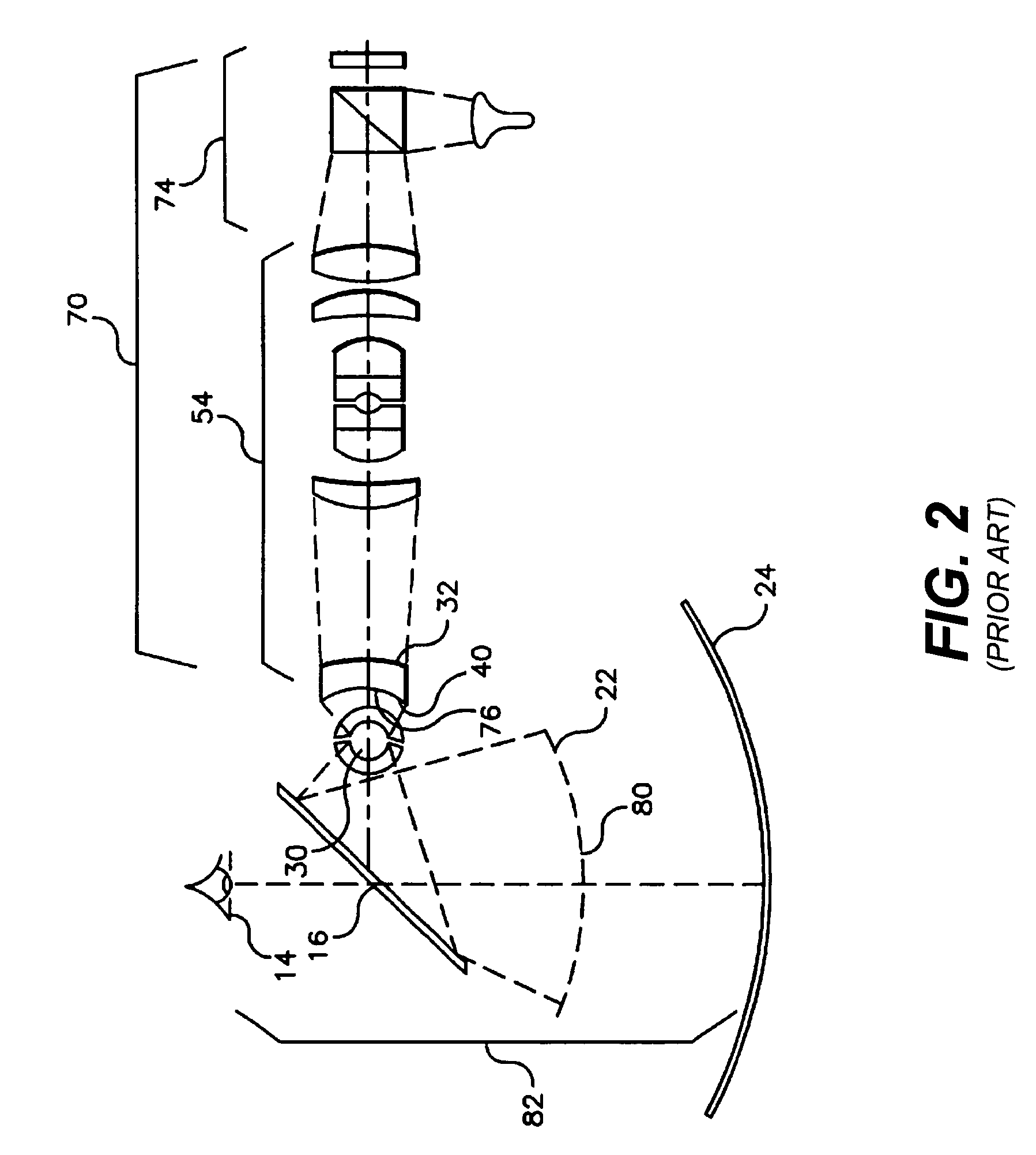
[0078]In order to better understand the operation and advantages of the present invention, it is useful to consider how optical assembly 110 is used in an autostereoscopic system. Referring to the single-mirror embodiment of FIG. 8, curved mirror 24 is slightly off center from both left exit pupil Pl and right exit pupil Pr. This off-center condition causes keystone distortion in the left virtual image and an opposing keystone distortion in the right virtual image. This distortion can be corrected by electronically pre-distorting the image data provided to left image source and to the right image source 100r, using image data manipulation techniques that are well known in the digital imaging art. Referring now to FIG. 4, there is shown an alternate embodiment that minimizes keystone distortion in the virtual images formed, since each exit pupil is on axis relative to its own curved mirror. In autostereoscopic display apparatus 10 of FIG. 4, left and right optical assemblies 110l and...


PUM

PropertyMeasurementUnit
diameteraaaaaaaaaa
diameteraaaaaaaaaa
sizeaaaaaaaaaa

Abstract

An autostereoscopic optical apparatus (10) for viewing a stereoscopic image comprising a left image to be viewed by an observer (12) at a left viewing pupil (14l) and a right image to be viewed by the observer at a right viewing pupil (14r). A left image generation system (70l) forms a left curved intermediate image near the focal surface (22) of a curved mirror (24). A right image generation system (70r) forms a right intermediate image near the focal surface of the curved mirror. A center of curvature of the curved mirror is placed substantially optically midway between the exit pupil and the left optical system (110l) the exit pupil of the right optical system (110r). A beamsplitter is disposed between the focal surface and the center of curvature of the curved mirror.

Description

CROSS REFERENCE TO RELATED APPLICATIONS[0001]Reference is made to commonly-assigned copending U.S. patent application Ser. No. 10 / 393,236, filed Mar. 20, 2003, entitled METHOD AND APPARATUS FOR MONOCENTRIC PROJECTION OF AN IMAGE, by Joshua M. Cobb; and U.S. patent application Ser. No. 10 / 662,208, filed Sep. 12, 2003, entitled AUTOSTEREOSCOPIC OPTICAL APPARATUS by Cobb et al.; the disclosures of which are incorporated herein.FIELD OF THE INVENTION[0002]This invention generally relates to display apparatus and more particularly relates to an image generation apparatus for an autostereoscopic display providing a wide field of view, large left and right viewing pupils, and high brightness, with improved cost and reduced size.BACKGROUND OF THE INVENTION[0003]The potential value of autostereoscopic display systems is well appreciated for a broad range of data visualization uses and for a wide range of applications that include entertainment, engineering, medical, government, security, and...

Claims


Application Information

Patent Timeline
Patent Type & Authority Patents(United States)
IPC IPC(8): G03B21/00G02B27/14G02B27/22G02B27/24G02F1/1335H04N13/04G02B30/26G02B30/60H04N13/00
CPCG02B27/225H04N13/0402H04N13/0443H04N13/302H04N13/346G02B30/26
Inventor COBB, JOSHUA M.
Owner EASTMAN KODAK CO
Why Eureka
Try Eureka