Apparatus for separating particles from a flowing medium

a technology of fluid medium and apparatus, applied in the direction of auxillary pretreatment, separation process, human health protection, etc., can solve the problem of high manufacturing cos

Active Publication Date: 2007-08-21
MANN HUMMEL GMBH
View PDF18 Cites 15 Cited by
  • Summary
  • Abstract
  • Description
  • Claims
  • Application Information

AI Technical Summary

Benefits of technology

[0007]Another object of the invention is to provide an apparatus for separating particles and / or liquid droplets from a gas stream which achieves a high degree of separation with a low pressure loss.
[0023]The method of the invention makes it possible to separate solid particles and / or liquid droplets from a flowing gas using a centrifugal separator with a minimum loss of pressure. In this method, the gas flowing through the inlet is caused to rotate by an inlet guide device. The rotating gas stream flows through a separating zone in which the particles are flung against the wall of the housing by centrifugal force. In the further course of the flow, the rotating gas stream moves through an outlet guide device, which causes the gas stream to flow in a straight line once again. The guide elements of the outlet guide device vane receive the helically flowing gas at an angle matching the helical flow angle and, due to their curvature, redirect the helical movement into a linear movement and stabilize the linear air flow. By these means, the rotational energy of the helical air flow is converted into a linear movement, and the pressure difference or pressure loss is thereby minimized.

Problems solved by technology

A disadvantageous aspect of this apparatus is its high manufacturing cost, which is necessary due to the arrangement of the individual air-guiding elements.

Method used


Image

  • Apparatus for separating particles from a flowing medium
  • Apparatus for separating particles from a flowing medium

Examples


Embodiment Construction

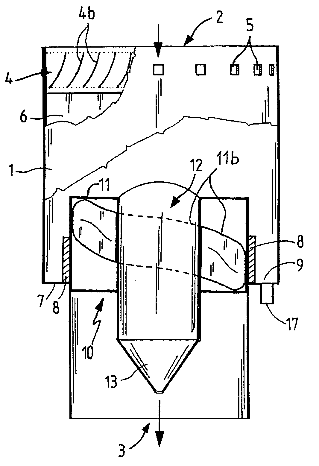
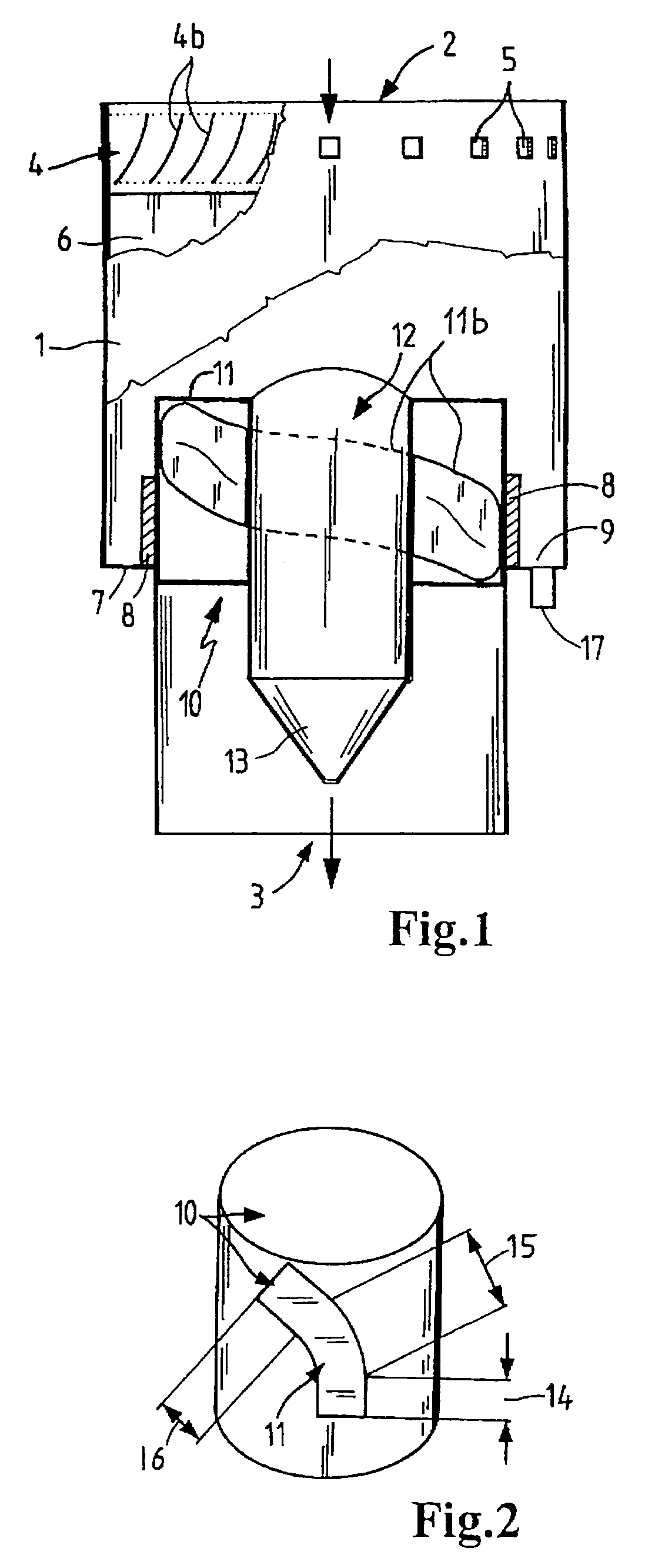
[0028]FIG. 1 shows a preferably hollow cylindrical housing 1 provided with an inlet 2 and an outlet 3. Furthermore, an inlet guide device 4 is clipped into recesses 5 in the housing 1. Separated particles are deposited at the housing wall in a separating zone 6. The separated particles are collected on a collecting base 7, which is disposed beneath the separating zone 6. A divider or separating element 8 prevents the separated particles from being re-entrained by the flowing air and, together with the collecting base 7, forms a collecting chamber 9. A discharge pipe 17 is arranged in the collecting base 7 and forms a connection for controlled discharge of the separated particles. An outlet guide device 10 comprises guide elements 11 and a cylindrical core 12. Outlet guide 10 is manufactured in one piece with the divider 8, the collecting base 7 and the housing 1.

[0029]In the drawing, the external contour of the guide elements 11 has a rectangular cross-section. The helical lines 11b...


PUM

PropertyMeasurementUnit
helical flow angleaaaaaaaaaa
diameteraaaaaaaaaa
centrifugal forceaaaaaaaaaa

Abstract

A separating apparatus which enables particles to be separated from a flowing medium by a preliminary separator which avoids the undesirably high pressure losses due to the flow resistance of known preliminary separators. The separating apparatus has a housing with an inlet and an outlet, in which a flow of air at the inlet end is caused to rotate by an inlet guide device, and is redirected again at the outlet end by an outlet guide device into a linear flow. The pressure recovery is achieved by a defined curvature and arrangement of the guide elements. The guide element curvature has an inlet contour, a retarding contour and a stabilizing contour. Preliminary separators of this type are used primarily in the air intake tracts of internal combustion engines exposed to heavy contamination, such as engines in farm machinery or construction machinery.

Description

BACKGROUND OF THE INVENTION[0001]The invention relates to an apparatus and method for separating solid particles and liquids from flowing gases.[0002]Separators of this type are used predominantly in the intake air of internal combustion engines if increased contamination and / or the presence of liquid droplets are generally expected as, for example, in engines for farm machinery and construction machinery of all types, as well as in commercial vehicles. Usually, these devices are used as preliminary separators.[0003]U.S. Pat. No. 3,064,411 discloses an apparatus which is intended to separate solids from a fluid medium and has the following characteristics. The cylindrical housing of the device tapers conically at its axial end faces, and the inlet and the outlet are disposed at the reduced diameters. An inlet guide vane is arranged on the inlet side and an outlet guide vane at the outlet side within the cylinder, which is tapered conically at both ends. Both guide devices are provid...

Claims


Application Information

Patent Timeline
Patent Type & Authority Patents(United States)
IPC IPC(8): B01D45/12B01D45/16B04C3/06F02M35/022
CPCB01D45/16B04C3/06F02M35/022B04C2003/006Y02A50/2351
Inventor GREIF, VOLKERHAEHN, JENS
Owner MANN HUMMEL GMBH
Why Eureka
Try Eureka