Display panel device

a display panel and panel technology, applied in the direction of instruments, machine supports, electrical apparatus casings/cabinets/drawers, etc., can solve the problems of not being able to reliably and effectively discharge heat generated in the device, providing sufficient increased display panel strength for sufficiently high rigidity, etc., to achieve simple structure, increase display panel strength, and high rigidity

Inactive Publication Date: 2007-09-11
SONY CORP
View PDF10 Cites 57 Cited by
  • Summary
  • Abstract
  • Description
  • Claims
  • Application Information

AI Technical Summary

Benefits of technology

[0005]It is therefore an embodiment of the present invention to provide a liquid crystal display panel device of simple structure which has increased display panel strength for higher rigidity and which is capable of discharging heat generated in the device reliably and effectively out of the device.
[0007]With the above arrangement, the left heat radiating plate, the right heat radiating plate, and the central rear cover are mounted on the rear side of the display panel, and the left heat radiating plate and the right heat radiating plate function as stiffening members having the mechanical strength of L-shaped angles and are of a substantially L-shaped cross section, the left heat radiating plate and the right heat radiating plate having the vertically extending supports near the center of the rear side of the display panel. Since the central rear cover extends and is secured in place between the supports, which confront each other, of the left heat radiating plate and the right heat radiating plate, the mechanical strength of the display panel is sufficiently increased, and the rigidity of the display panel device is also sufficiently increased.
[0008]As the left heat radiating plate and the right heat radiating plate cover left and right areas of the rear side of the display panel and have their supports joined to the central rear cover, heat generated in the display panel device is reliably and effectively radiated out of the display panel device.
[0009]If the central rear cover includes a heat radiating plate having a plurality of fins, then the central rear cover can easily be formed as an aluminum extrusion or the like. Since the central rear cover with the fins extend over a wide central area of the rear side of the display panel, the rear side of the display panel device provides excellent designability for better functional appearance.

Problems solved by technology

However, the liquid crystal display panel device of the above construction fails to provide sufficiently increased display panel strength for sufficiently high rigidity and also fails to discharge heat generated in the device reliably and effectively out of the device.

Method used


Image

  • Display panel device
  • Display panel device
  • Display panel device

Examples


Embodiment Construction

1. Self-Standing Display Panel Device (FIGS. 1 to 5):

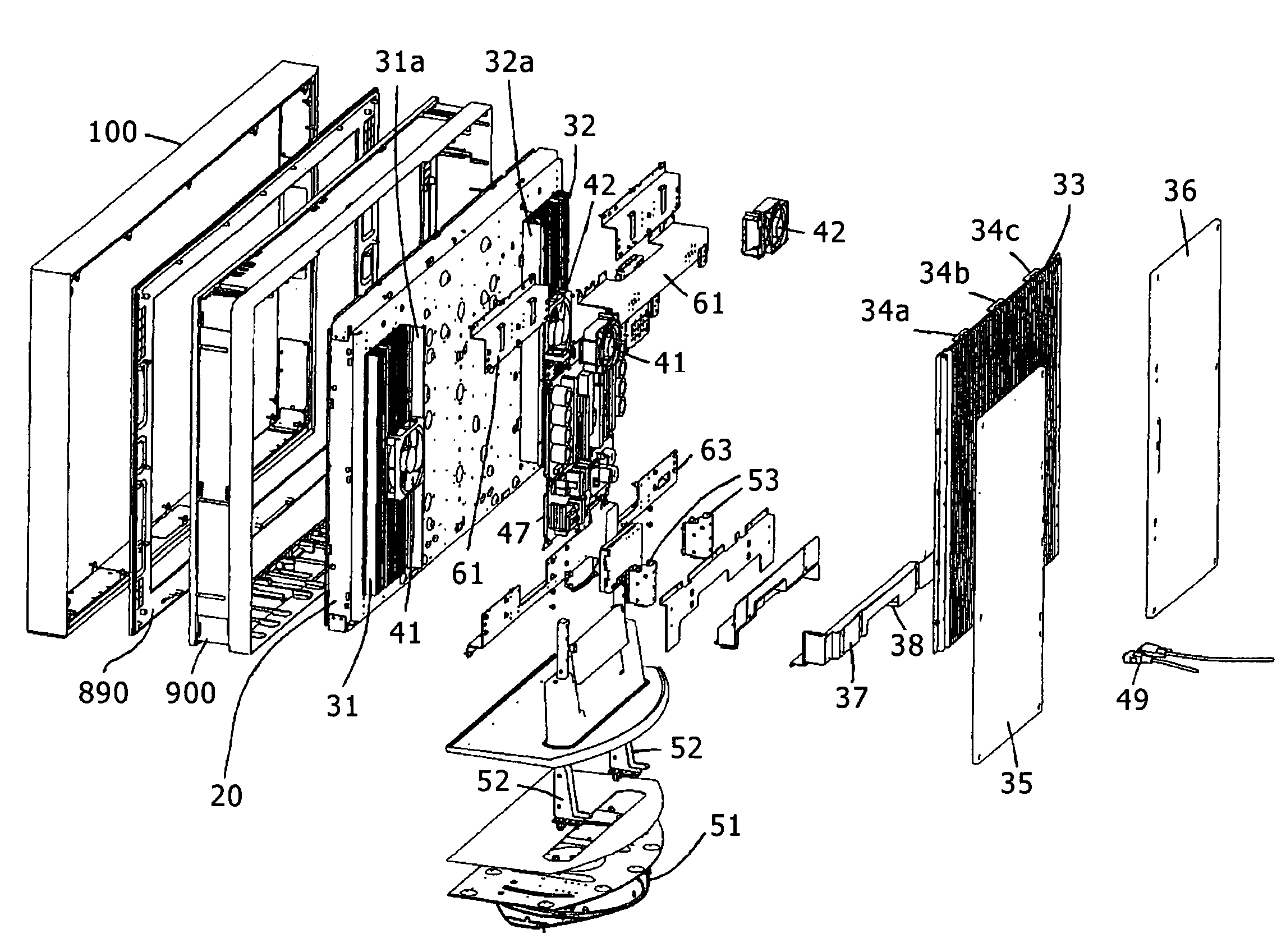
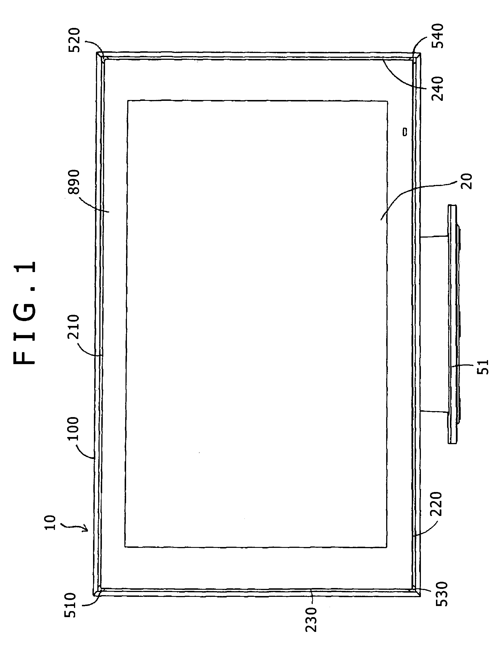
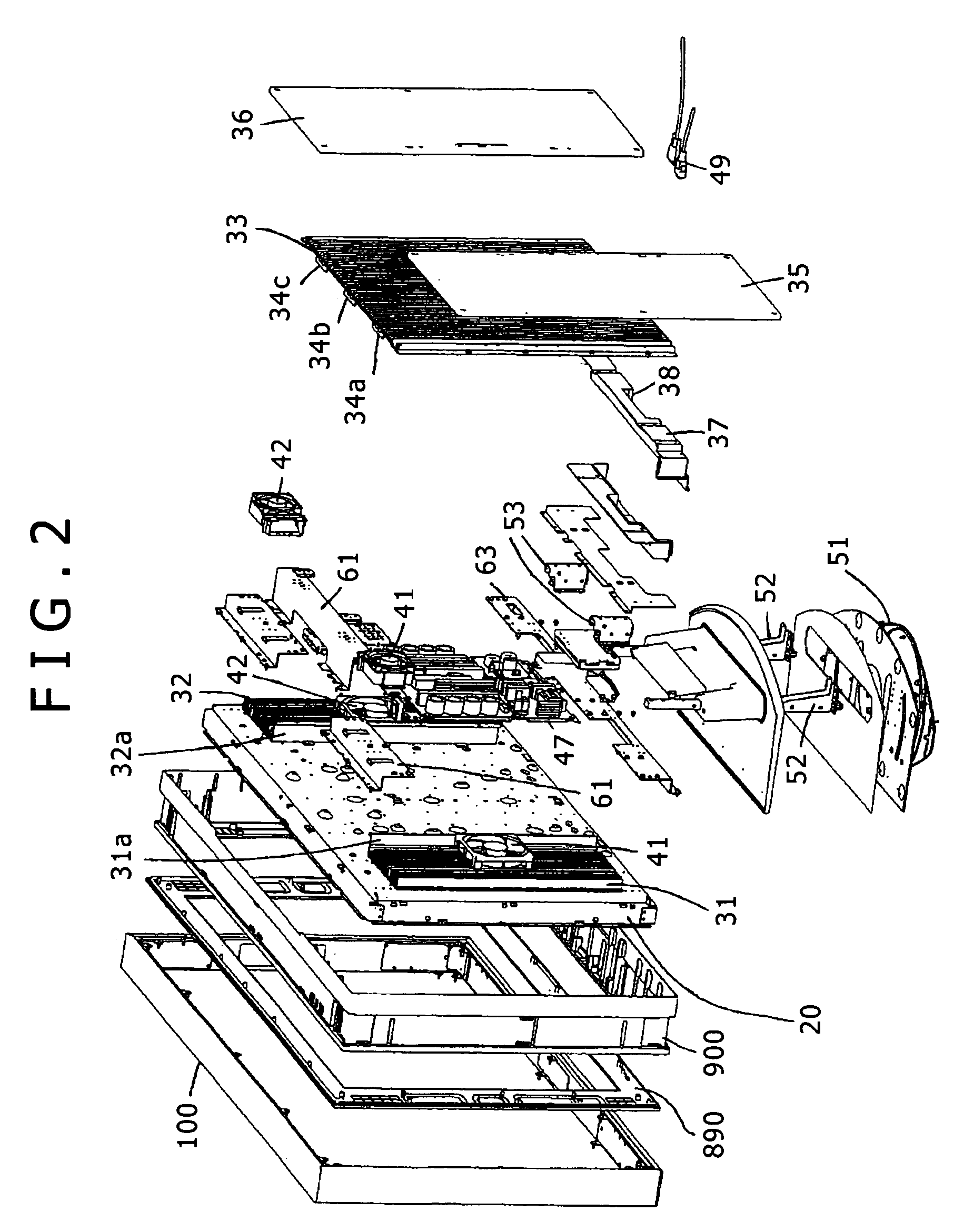
[0018]As shown in FIG. 1, a display panel device according to the present invention, which is constructed as a self-standing liquid crystal display panel device, includes a frame assembly 10 and a liquid crystal display panel 20 which are mounted on a stand 51.

[0019]The frame assembly 10 includes an outer frame 100, an inner frame (cabinet) that is omitted from illustration in FIG. 1, a transparent upper side plate 210, a transparent lower side plate 220, a transparent left side plate 230, and a transparent right side plate 240 which are interposed between the outer frame 100 and the inner frame. The outer frame 100 has upper left, upper right, lower left, and lower right corners combined with respective corner covers 510, 520, 530 and 540.

[0020]The transparent upper side plate 210, the transparent lower side plate 220, the transparent left side plate 230, and the transparent right side plate 240 serve to create a floating effect ...


PUM


Abstract

Left and right heat radiating plates are mounted on the rear side of a liquid crystal display panel in respective left and right positions thereon. The left and right heat radiating plates are of a substantially L-shaped cross section including a plurality of fins and respective supports near the center of the rear side of the liquid crystal display panel. A central rear cover has a plurality of fins and has left and right ends fixedly mounted respectively on the supports of the left and right heat radiating plates in covering relation to a circuit assembly on the rear side of the liquid crystal display panel. Left and right rear covers are mounted respectively on rear sides of the left and right heat radiating plates and lie substantially flush with the central rear cover.

Description

BACKGROUND OF THE INVENTION[0001]The present invention relates to a display panel device such as a liquid crystal display panel device or the like.[0002]Display panel devices such as liquid crystal display panel devices or the like which have large screen sizes are required to have increased display panel strength for higher rigidity and also to discharge heat generated in the devices reliably and effectively out of the devices.[0003]Japanese Patent Laid-open No. 2003-150076 discloses a liquid crystal display panel device having a liquid crystal display panel that is fixed to a front cover by left, right, and central stays extending in the transverse direction of the front cover and pressing peripheral edges of the liquid crystal display panel. The disclosed liquid crystal display panel device also has a planar rear cover mounted on the rear side of the liquid crystal display panel.[0004]However, the liquid crystal display panel device of the above construction fails to provide suff...

Claims


Application Information

Patent Timeline
Patent Type & Authority Patents(United States)
IPC IPC(8): H05K5/00
CPCF16M11/10G02F1/133308G02F1/133385G06F1/203H05K7/20972F16M2200/061G02F2001/133314G02F2001/133328G02F1/133314G02F1/133328G06F1/1601
Inventor NAGANO, MASAHIRO
Owner SONY CORP
Why Eureka
Try Eureka