Equipment enclosure kit and assembly method

Active Publication Date: 2007-11-13
SCHNEIDER ELECTRIC IT CORP
View PDF15 Cites 260 Cited by
  • Summary
  • Abstract
  • Description
  • Claims
  • Application Information

AI Technical Summary

Problems solved by technology

Further, with the ever decreasing size of computer equipment, and in particular, computer servers, the number of electrical connectors mounted in each rack has been increasing, raising additional power distribution, cooling and cable distribution concerns at the rack level.

Method used


Image

  • Equipment enclosure kit and assembly method
  • Equipment enclosure kit and assembly method
  • Equipment enclosure kit and assembly method

Examples


Embodiment Construction

[0087]For the purposes of illustration only, and not to limit the generality, the present invention will now be described in detail with reference to the accompanying figures. This invention is not limited in its application to the details of construction and the arrangement of components set forth in the following description or illustrated in the drawings. The invention is capable of other embodiments and of being practiced or being carried out in various ways. Also the phraseology and terminology used herein is for the purpose of description and should not be regarded as limiting. The use of “including,”“comprising,”“having,”“containing”“involving,” and variations thereof herein, is meant to encompass the items listed thereafter and equivalents thereof as well as additional items.

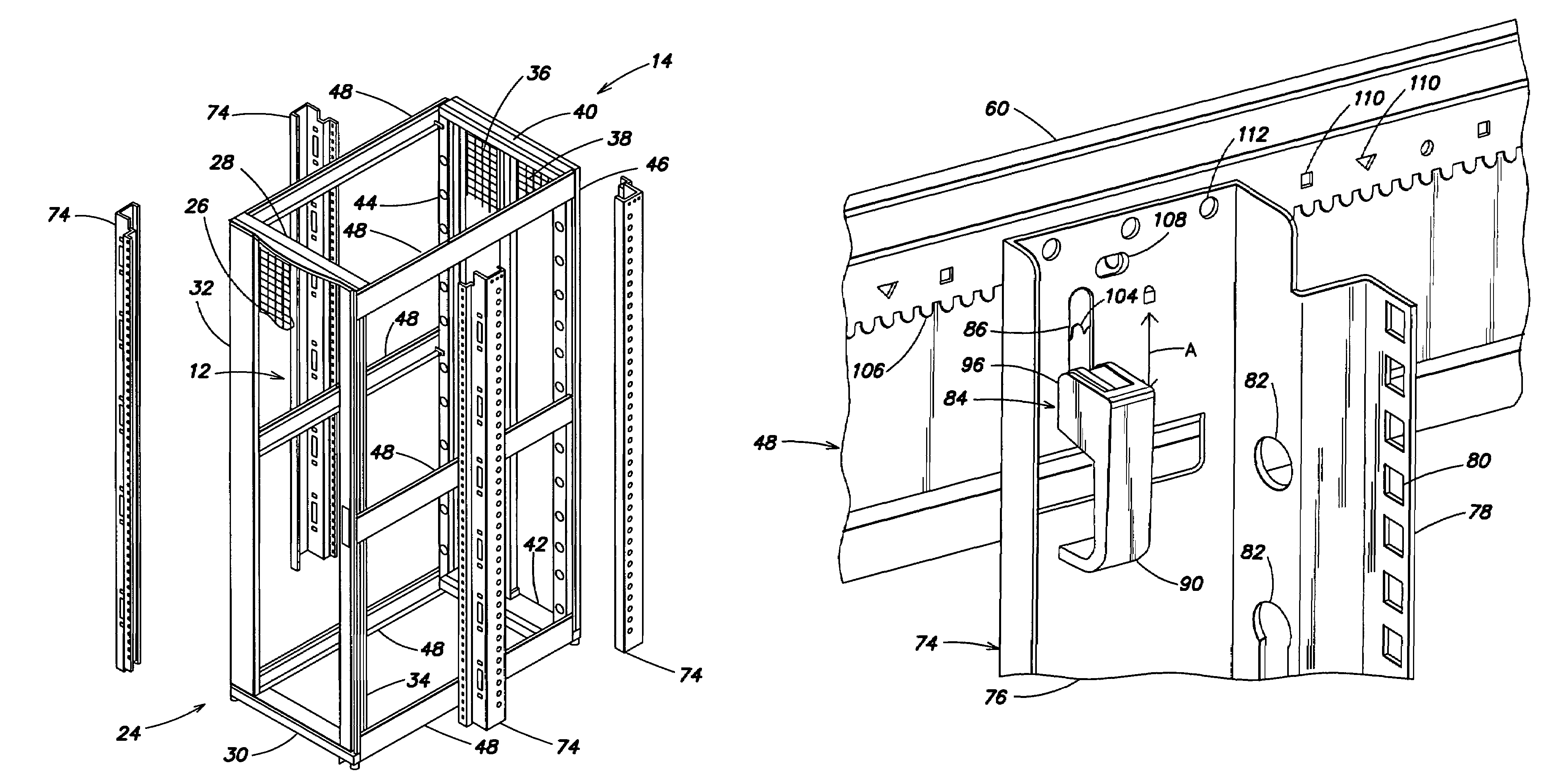
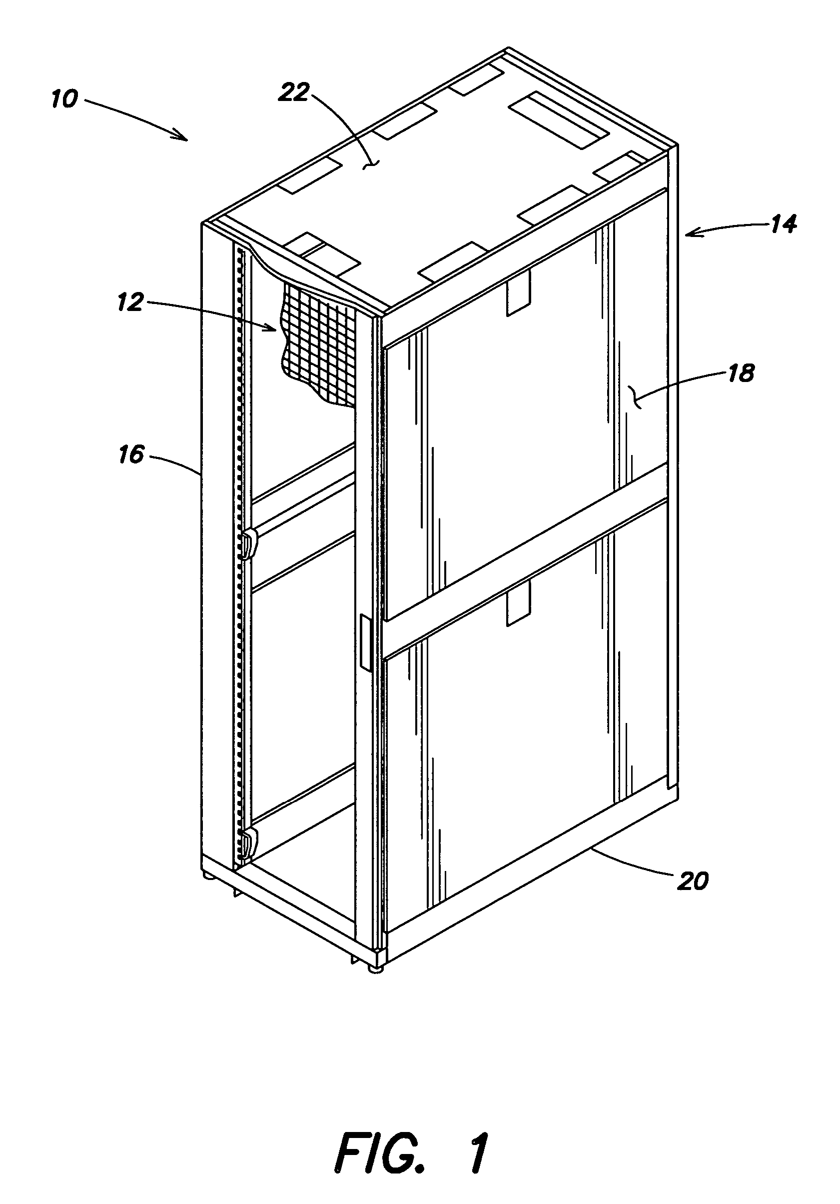
[0088]Referring to the drawings, and more particularly to FIG. 1, there is generally indicated at 10 an enclosure in accordance with at least one embodiment of the present invention to house electronic e...


PUM


Abstract

An equipment enclosure for housing electronic components includes a front assembly having a front frame, the front assembly defining a front of the enclosure, and a rear assembly having a rear frame. The enclosure further includes at least two side brace members, each side brace member having a first end and a second, opposite end. A first connector is configured to releasably connect the first end of one of the side brace members to the front frame. A second connector is configured to releasably connect the second end of the one of the side brace members to the rear frame. Other embodiments and methods are further disclosed.

Description

BACKGROUND OF THE INVENTION[0001]1. Field of the Invention[0002]The present invention relates to racks and enclosures, and more particularly to racks and enclosures used to house data processing, networking and telecommunications equipment.[0003]2. Discussion of Related Art[0004]Equipment enclosures for electronic equipment, such as data processing, networking and telecommunications equipment have been in use for years. Over the years, a number of different standards have been developed to enable equipment manufacturers to design rack mountable equipment that can be mounted in standard racks manufactured by different manufacturers. One such standard is the Electronic Industries Association's EIA-310-D standard which defines parameters for what has become an industry standard nineteen inch rack.[0005]Nineteen inch racks are used extensively in data centers and other facilities. With the proliferation of the Internet, it is not uncommon for a data center to contain hundreds of these r...

Claims


Application Information

Patent Timeline
Patent Type & Authority Patents(United States)
IPC IPC(8): A47B43/00
CPCG06F1/181G06F1/183H05K7/183F16B7/044H05K5/0226H01R11/01Y10T403/4602Y10T403/64Y10T403/595F16B2200/50H05K7/1488
Inventor MATTLIN, JEFFREY LEEBERGESCH, JOSEPH H.THOMAS, KEVIN NEILSMITH, PAUL THOMASSPITAELS, JAMES S.BRYAN, DANIEL
Owner SCHNEIDER ELECTRIC IT CORP
Why Eureka
Try Eureka