Assembly method and structure of an electronic clinical thermometer

a technology assembly methods, which is applied in the field of assembly methods and structure of electronic clinical thermometers, can solve the problems of inability to replace reference resistors and temperature sensors, high cost of electronic thermometers currently on the market, and short measurement time requirements, so as to reduce the size of the thermometer, easy to read the temperature, and easy to measure the temperature

Inactive Publication Date: 2007-11-13
ACTHERM INC
View PDF16 Cites 19 Cited by
  • Summary
  • Abstract
  • Description
  • Claims
  • Application Information

AI Technical Summary

Benefits of technology

[0013]It is another object of the present invention to provide a structure of an electronic clinical thermometer which includes a measuring body with an incomplete electronic clinical thermometer circuit controlled by an integrated circuit and which requires at least two fewer elements (such as reference resistor and temperature sensor), and a temperature sensing device containing at least two fewer elements in the measuring body, and a connecting structure arranged between the measuring body and the temperature sensor and being conductive, so that the measuring body and the temperature sensor can be disengaged from each other or engaged together to form a complete electronic clinical thermometer.
[0014]It is still another object of the present invention to provide an electronic clinical thermometer which enables a user to read the temperature easily, and which has a backlight device to make it easier to read the temperature and a delayed circuit and a reset circuit so that when the measured temperature is stabilized, a buzzer will produce a humming sound and / or a light source will give light to notify the user of the peak temperature, and the backlight device will be activated within a predetermined period of time after the stabilized temperature is obtained thereby making it easier to read the measured temperature. If the user cannot read the temperature clearly within the time period when the backlight device is turned on, the user may press and hold the switch to activate the backlight device to give light until the switch is released and turned off.
[0015]It is a further object of the present invention to provide an electronic clinical thermometer which has a sheet-like buzzer mounted on an opening of the circuit board of the measuring body thereby eliminating the sound case of the conventional buzzer and therefore reducing the size of the thermometer.

Problems solved by technology

The reference resistor and the temperature sensor of the conventional electronic thermometer are fixedly mounted on the measuring circuit board, so that the resistance matching result of the reference resistor and the temperature sensor cannot be replaced.
Furthermore, the time required for measuring is very short.
The electronic thermometers currently on the market are expensive, and so cannot be disposed of after use, and must be cleaned by means of a long, complicated sterilizing procedure before being able to be safely used again.
Moreover, the display of most of the conventional thermometers does not have a backlight generator.
Some conventional thermometers have a backlight generator, but the backlight generator can only give light for a very short period of time, so that when the user takes up the thermometer to read the temperature value, the backlight will be off thereby making it difficult to read the temperature and therefore causing much inconvenience in use.

Method used


Image

  • Assembly method and structure of an electronic clinical thermometer
  • Assembly method and structure of an electronic clinical thermometer
  • Assembly method and structure of an electronic clinical thermometer

Examples


Embodiment Construction

[0027]The following descriptions are of exemplary embodiments only, and are not intended to limit the scope, applicability or configuration of the invention in any way. Rather, the following description provides a convenient illustration for implementing exemplary embodiments of the invention. Various changes to the described embodiments may be made in the function and arrangement of the elements described without departing from the scope of the invention as set forth in the appended claims.

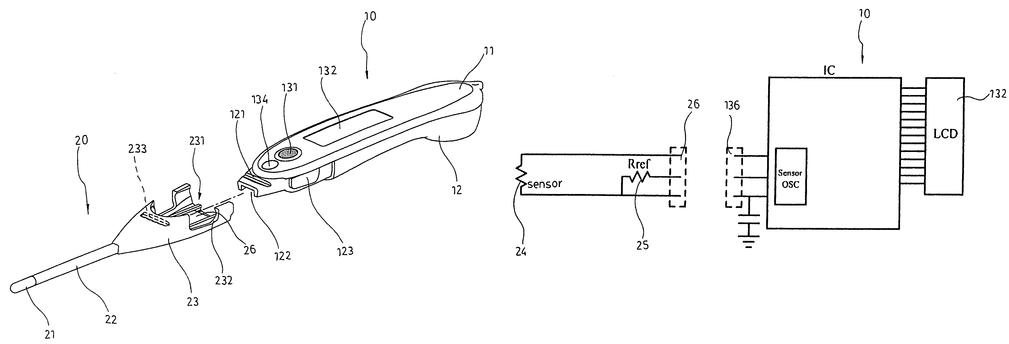
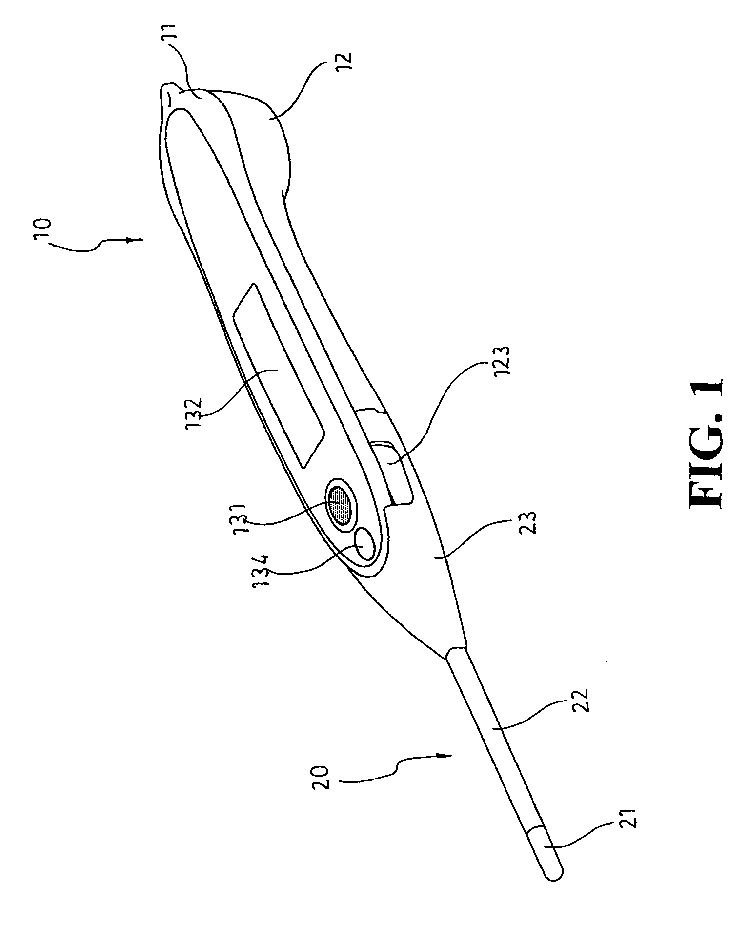
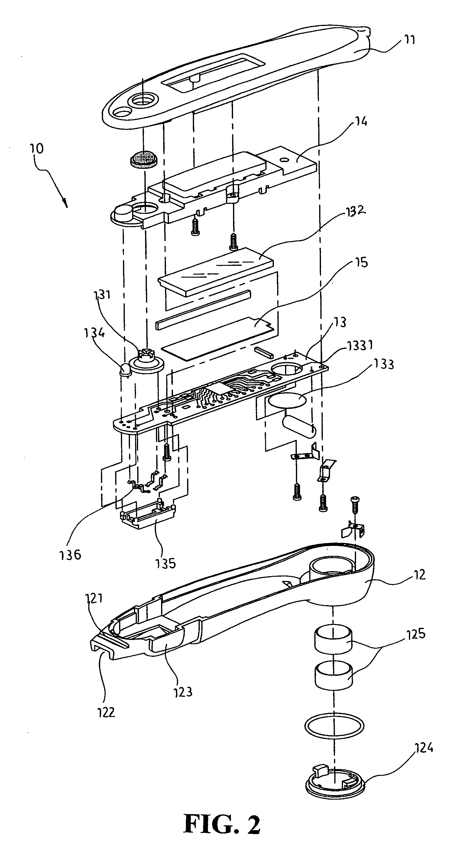
[0028]Referring to FIGS. 1, 2, and 3, the electronic clinical thermometer according to the present invention comprises two detachable modules, i.e. the measuring body 10 and the sensing device 20.

[0029]The measuring body 10 comprises a top cover 11 and a bottom cover 12 made from hard plastic material. The front section of the bottom cover 12 is formed with a slot 121 on the top and a recess 122 on the bottom. Two lateral sides of the front section of the bottom cover 12 are each formed with an e...


PUM

PropertyMeasurementUnit
temperatureaaaaaaaaaa

Abstract

An assembly method and structure of an electronic clinical thermometer is disclosed. The thermometer can be disassembled or assembled as required, wherein one of the detachable modules such as the measuring body has an incomplete electronic clinical thermometer circuit lacking at least two elements, and these electronic elements are mounted within the other module such as the measuring probe, so that the two modules when attached together form a complete clinical thermometer.

Description

BACKGROUND OF THE INVENTION[0001](a) Field of the Invention[0002]The present invention relates to a assembly method and structure of an electronic clinical thermometer, and in particular to a clinical thermometer which can be disassembled or assembled as required, wherein one of the detachable modules such as the measuring body has an incomplete electronic clinical thermometer circuit lacking at least two elements, and these electronic elements are mounted within the other module such as the measuring probe, so that the two modules when attached together form a complete clinical thermometer for measuring the temperature of patients.[0003](b) Description of the Prior Art[0004]Before the invention of electronic thermometers, mercury thermometers were widely used for measuring body temperature. Mercury will expand when subject to heat and contract when subject to cold. When in measuring, the mercury in the measuring probe will expand so that the mercury will go into a capillary tube ma...

Claims


Application Information

Patent Timeline
Patent Type & Authority Patents(United States)
IPC IPC(8): G01K7/16A61B5/01G01K1/16
CPCG01K13/002G01K13/20
Inventor CHEN, SANLIAN
Owner ACTHERM INC
Why Eureka
Try Eureka