Accessory lock assembly

a technology of accessory locks and locks, applied in the field of accessory locks, can solve the problems of affecting etc., and causing the connection between the first and the inner knob frame to be broken. , to achieve the effect of ensuring the appearance of the accessory lock, and ensuring th

Inactive Publication Date: 2008-02-26
PATH LINE NGS HLDG
View PDF16 Cites 9 Cited by
  • Summary
  • Abstract
  • Description
  • Claims
  • Application Information

AI Technical Summary

Benefits of technology

[0010]A main object of the present invention is to provide an accessory lock assembly comprising an outer knob assembly and an inner knob assembly the connection of which is substantially protected from unauthorized or unwanted damaged so as to prevent the accessory lock assembly from detaching from a door on which the accessory lock assembly is mounted as a result of the damage.
[0011]Another object of the present invention is to provide an accessory lock assembly comprising a lock reinforcing arrangement which is arranged to engage with a door on which the accessory lock assembly is mounted for effectively sharing the strength of the door so as to maximize resistibility upon impacts and excessive twisting.
[0012]Another object of the present invention is to provide an accessory lock assembly comprising a lock reinforcing arrangement which comprises a latch guider adapted to transversely bias against the outer knob housing and the inner knob assembly so as to substantially resist a damaging transverse or twisting force applied thereto. Moreover, the latch guider is arranged to engage with the door so as to distribute externally applied forces to the door for strengthening the accessory lock assembly.
[0014]Another object of the present invention is to provide an accessory lock assembly comprising a lock reinforcing arrangement which does not involve complicated or expensive mechanical components so as to minimize the manufacturing cost and the selling price of the present invention in order that the accessory lock assembly of the present invention can be widely accepted by public, thus increasing their security awareness.

Problems solved by technology

Unfortunately, very often, the outer protective housing is not strong enough both in terms of the materials used and its structure so that an intentional trespasser, by strongly twisting the actuation unit or vigorously breaking the outer protective housing, can be able to destroy the door lock and open the door.
Even though the outer protective housing is not broken altogether by the external force, such a substantial impact may have caused considerable distortion to it which then becomes extremely vulnerable to future damages.
Second, the connection between the outer protective housing and the inner knob frames is usually not strong enough so that when a trespasser applies vigorous impact to the door lock, the connection between the first and the inner knob frame will be broken altogether and, as a result, the outer protective housing and the inner knob frame and the actuation unit may detach from the door and leave the door unlocked immediately.
However, usually, such connecting screws can be screwed from the inner knob frame, such that when the door lock is mounted on a glass door, an intentional trespasser may easily break the glass and then put his / her hands inside the room for screwing out the connecting screws from inside the glass door.
As a result, the door lock is easily detached from the glass door, leaving the room unprotected.
As can be seen from these figures, there exist a very high official standard expected from a qualify door lock, and in respect of this, most conventional door locks fail to achieve the required standard.

Method used


Image

  • Accessory lock assembly
  • Accessory lock assembly
  • Accessory lock assembly

Examples


Embodiment Construction

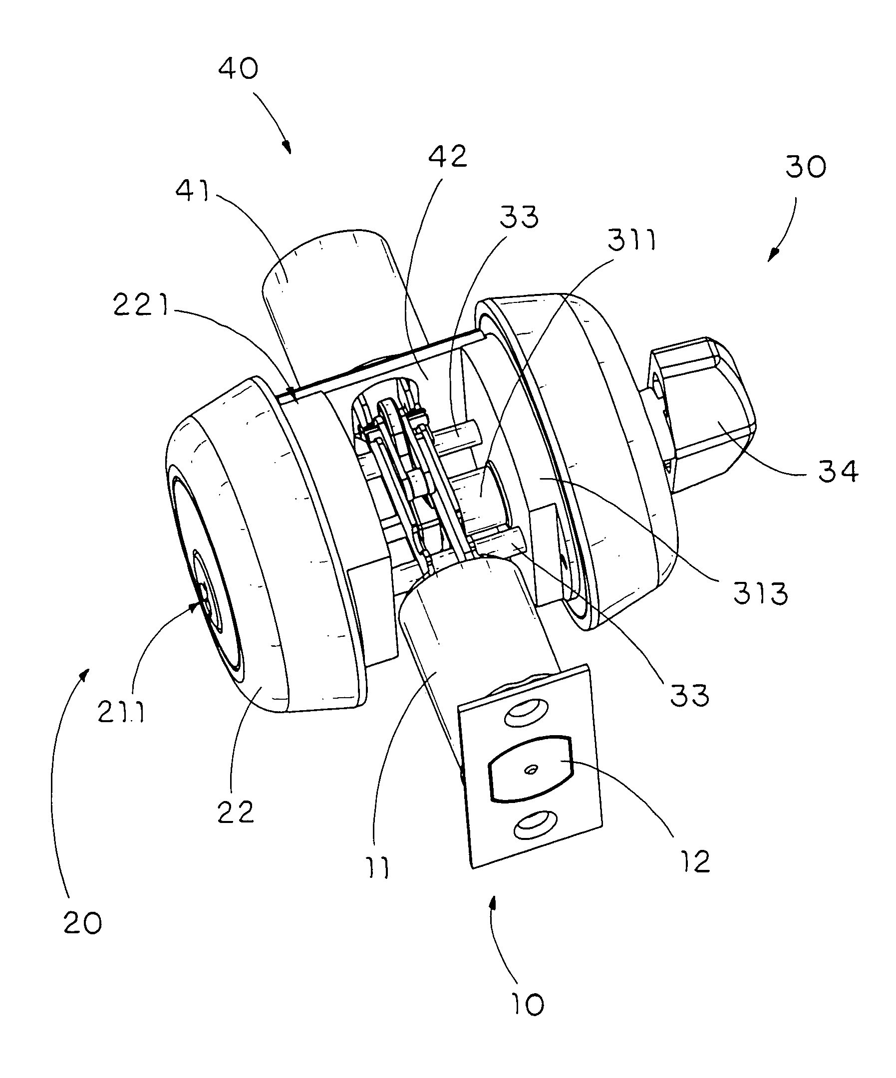
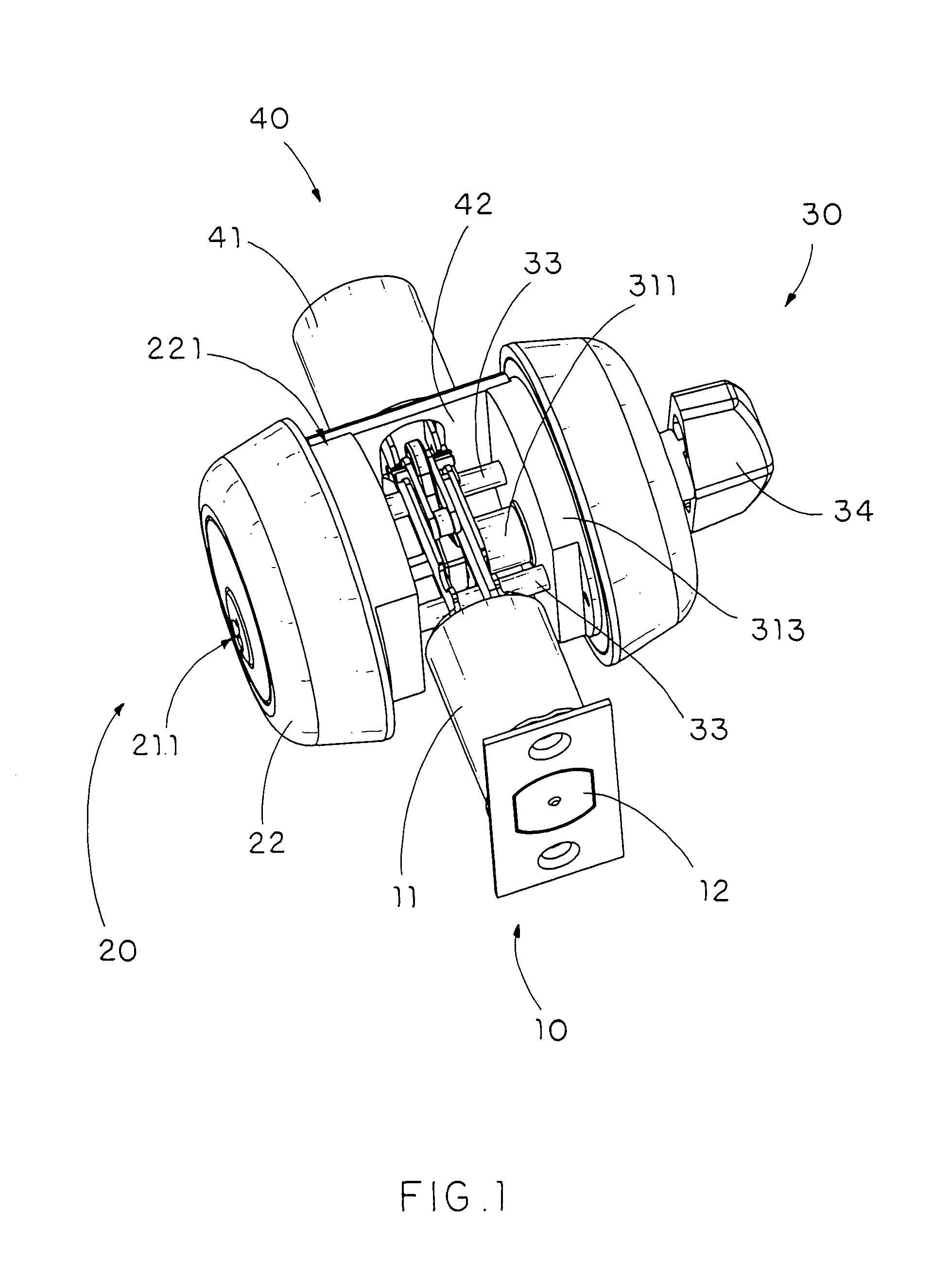
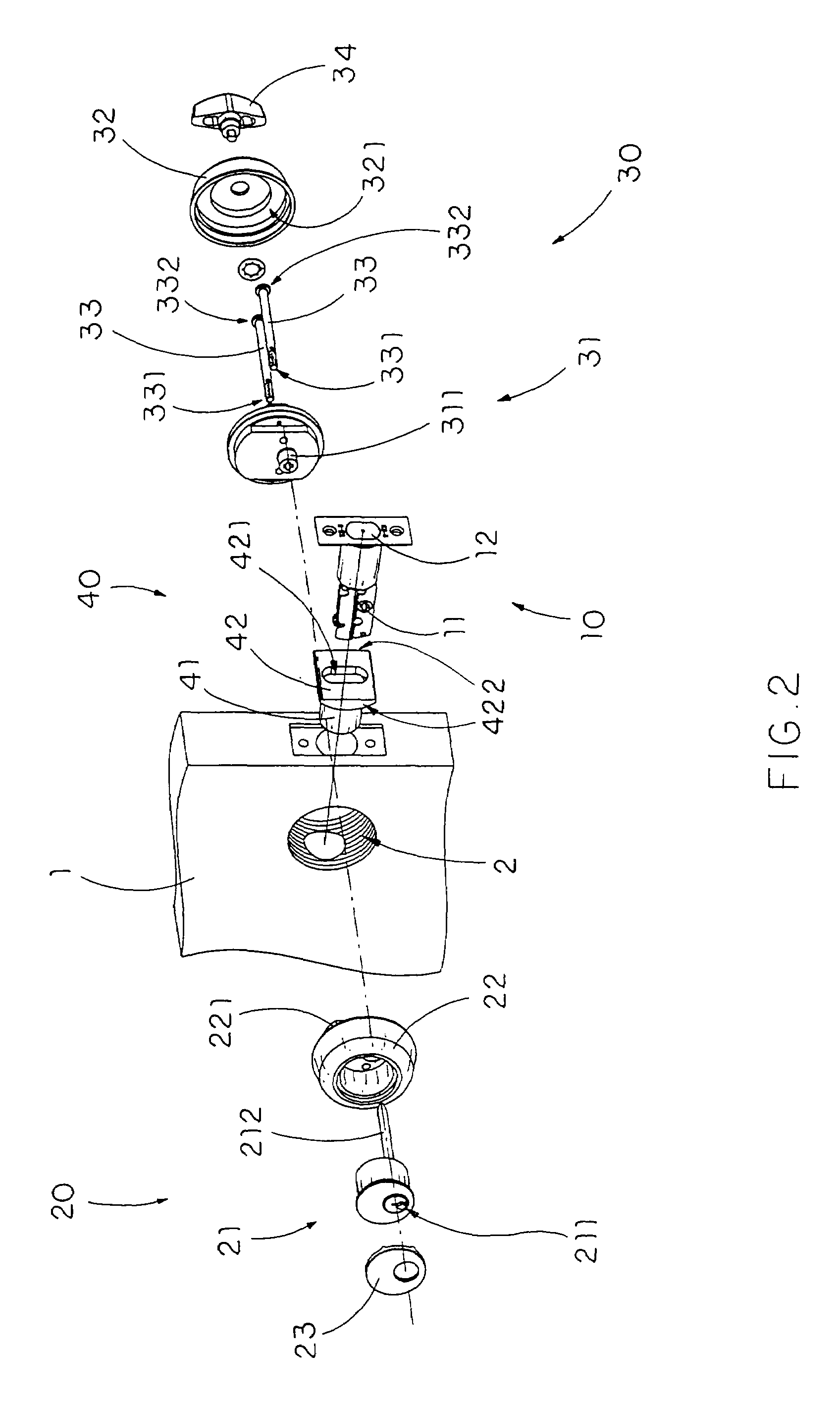
[0036]Referring to FIGS. 1 through 4 of the drawings, an accessory lock assembly according to a preferred embodiment of the present invention is illustrated, wherein the accessory lock assembly is adapted for locking a door panel 1 having a lock cavity 2 to a door frame in a pivotally movable manner.

[0037]The accessory lock assembly comprises a latch assembly 10, an outer knob assembly 20, an inner knob assembly 30, and a lock reinforcing arrangement 40.

[0038]The latch assembly 10 comprises a latch actuation member 11 adapted for transversely supporting within the lock cavity 2 and a locking latch 12 slidably extended from the latch actuation member 11 between a locked position and an unlocked position, wherein at the locked position, the locking latch 12 is outwardly slid for engaging with the door frame so as to lock up the door panel 1 within the door frame, and at the unlocked position, the locking latch 12 is inwardly slid for receiving in the lock cavity 2 such that the door p...


PUM


Abstract

An accessory lock assembly includes a latch assembly, an outer knob assembly mounted on one side of a door panel to connect with the latch assembly, an inner knob assembly mounted on another side of the door panel to connect with the latch assembly, and a lock reinforcing arrangement engaged between the outer and inner knob assemblies to block rotational movements of the outer and inner knob assemblies with the door panel. The inner knob assembly includes an inner actuation unit connecting with the latch assembly and at least a security binding element having a securing end connected to the outer knob assembly and an opposed operating end securely connected to the inner actuation unit within a receiving cavity of a protection shelter in such a manner that the operating end of the connecting element is isolated from outside of the accessory lock assembly by the protection shelter.

Description

BACKGROUND OF THE PRESENT INVENTION[0001]1. Field of Invention[0002]The present invention relates to locks, and more particularly to a lock enhancing device which is arranged to reinforce the strength of conventional locks so as to prevent them from being easily damaged, thus failure to provide sound security.[0003]2. Description of Related Arts[0004]A wide variety of locks have been widely used for security purposes. A conventional door lock which is incorporated in a door usually comprises an actuation unit which has a key slot formed therein, a knob assembly comprising an outer protective housing and an inner knob frame attached on an outer and an inner side of a door panel respectively wherein the actuation unit is mounted in the outer protective housing in a rotatably movable manner, and a locking latch mounted between the outer protective housing and the inner knob frame in such a manner that the actuation unit, upon being inserted with a predetermined key, is adapted to drive...

Claims


Application Information

Patent Timeline
Patent Type & Authority Patents(United States)
IPC IPC(8): E05B13/10E05B9/08E05B17/20E05B65/06
CPCE05B9/082E05B17/2084Y10S292/51Y10T70/5341Y10T70/5487Y10T70/5832Y10T70/7655Y10T70/8541Y10T70/8973Y10T292/57Y10T292/62
Inventor RUAN, JIAQIANG
Owner PATH LINE NGS HLDG
Why Eureka
Try Eureka