Portable storage container

a storage container and portability technology, applied in the field of portability storage containers, can solve the problems that the storage container may not have the strength to accommodate such loads, and achieve the effect of preventing accidental dislodgment of the bail member and improving the strength and reliability of the bail member

Active Publication Date: 2008-02-26
REHRIG PACIFIC CO INC
View PDF91 Cites 3 Cited by
  • Summary
  • Abstract
  • Description
  • Claims
  • Application Information

AI Technical Summary

Benefits of technology

[0003]A container according to one embodiment of the present invention provides a nest position and three selectable heights for the support portions of the bail members. The bail members can be adjusted to support similar containers stacked thereon according to how much is in the container. Additionally, the container provides improved strength and reliability of the bail members, and prevents accidental dislodgement of the bail members from their selected positions.
[0004]The container includes a plurality of walls extending upwardly from a floor. At least one of the walls includes an inner wall portion and an outer wall portion. At least one of the inner and outer wall portions has an elongated pin opening. A pair of bail members are each movable among a nest position, an upper stack position, a middle stack position and a lower stack position. Each bail member includes a support portion and arm extending transversely from outer ends of the support portion. A pin extends transversely from an outer end of each arm. Each pin is received in one of the pin openings, with the arm received between the inner and outer wall portions. The pins are slidable and pivotable in the pin openings to move the bail members to the various positions. Because the arms of the bail members are received between the inner and outer wall portions, accidental dislodgement of the bail member pins from the pin openings is prevented.

Problems solved by technology

Unfortunately, some containers may not have sufficient strength to accommodate such loads in a stack.

Method used


Image

  • Portable storage container
  • Portable storage container
  • Portable storage container

Examples


Embodiment Construction

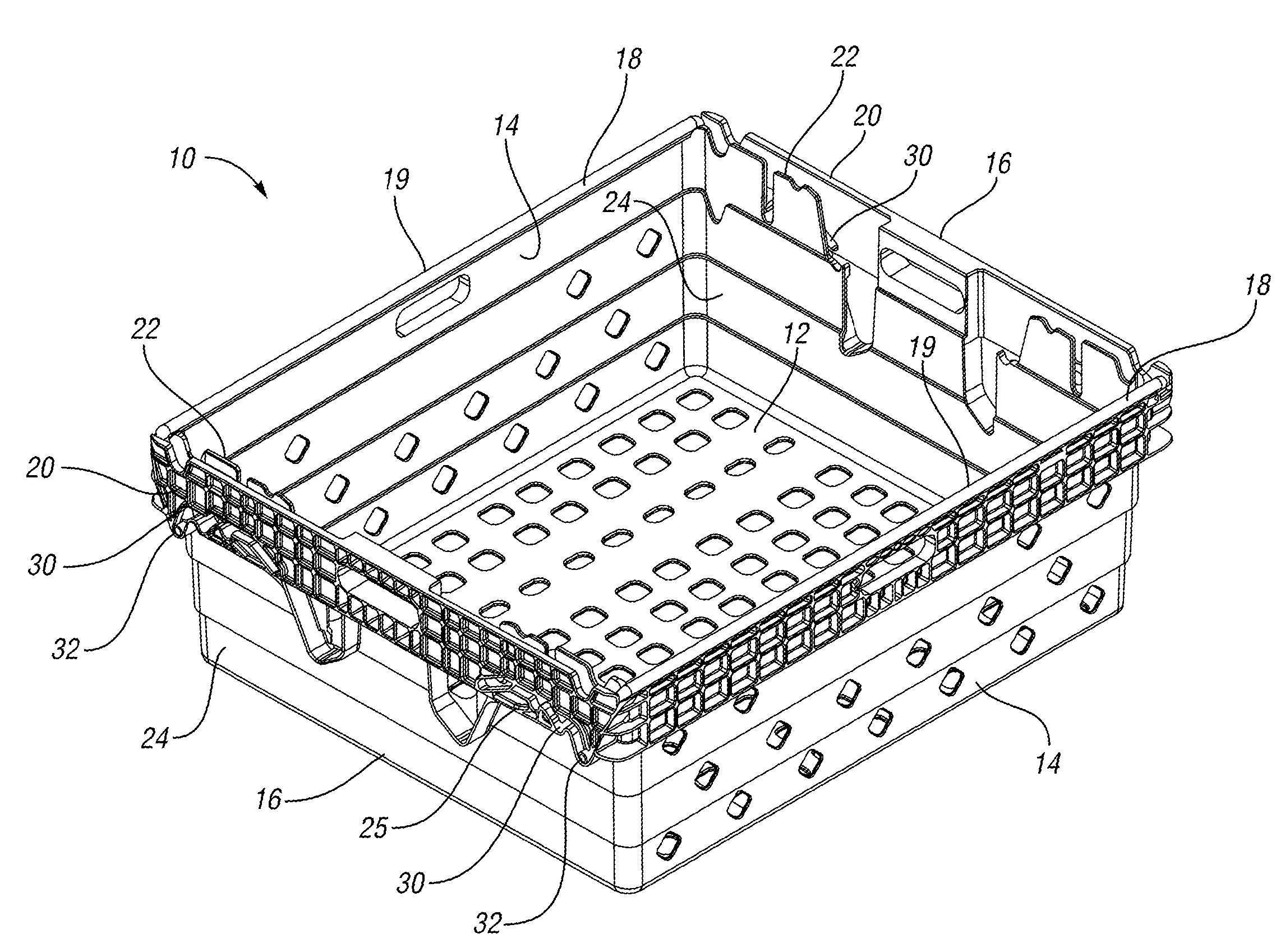
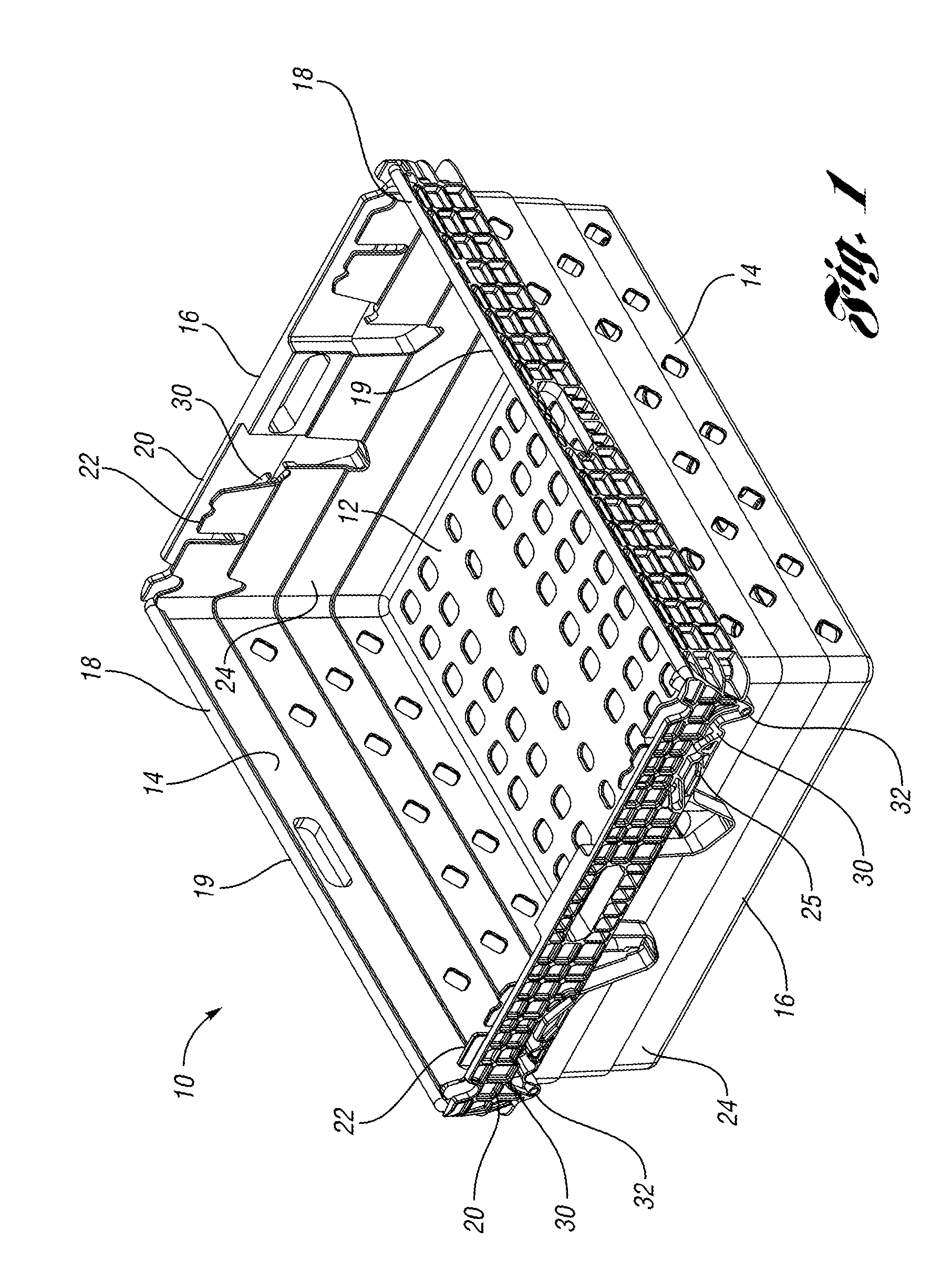
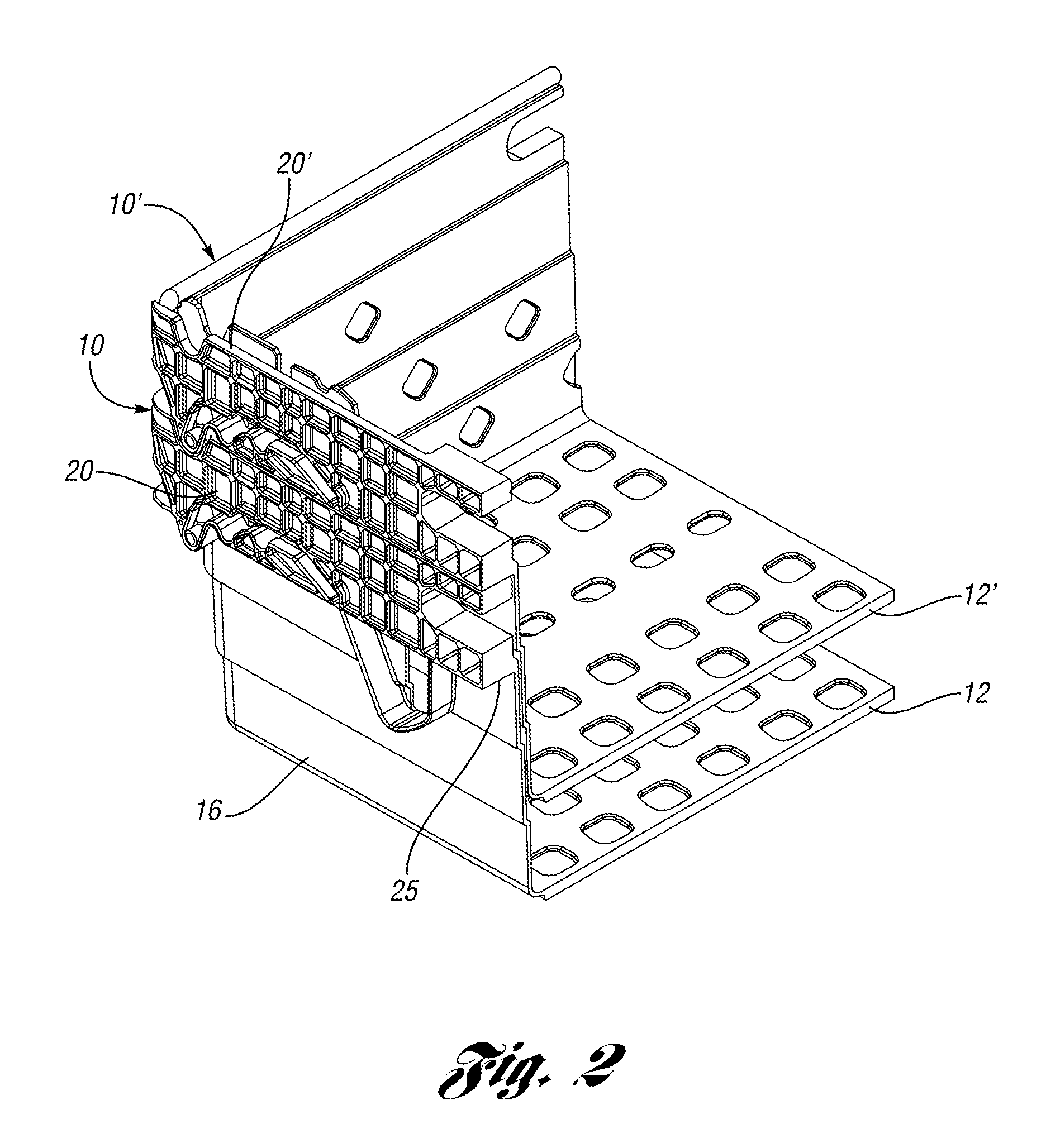
[0032]A container 10 according to the present invention is shown in FIG. 1. The container 10 includes a floor 12 and a pair of opposed side walls 14 and a pair of opposed end walls 16. A pair of bail members 18 are each mounted to each end wall 16, such that a support portion 19 of each bail member 18 extends across the length of the container 10. The end walls 16 each include an upper wall portion that has an outer wall portion 20 spaced from an inner wall portion 22. A lower wall portion 24 is generally aligned below the inner wall portion 22, such that the outer wall portion 20 forms a ledge 25 along the end wall 16.

[0033]Elongated pin openings 30 are formed in each outer wall portion 20 to trap pins 32 at the outer ends of the bail members 18. The pins 32 are slidable and pivotable within the pin openings 30, such that the bail members 18 can be moved to a plurality of positions and orientations. In FIGS. 1 and 2, the bail members 18 are in the nest position, where the support p...


PUM


Abstract

A portable storage container that both stacks and nests with similar containers includes a plurality of walls extending upwardly from a floor. At least one of the walls includes an inner wall portion and an outer wall portion. At least one of the inner and outer wall portions has an elongated pin opening. A pair of bail members are each movable among a nest position, an upper stack position, a middle stack position and a lower stack position. Each bail member includes a support portion and arm extending transversely from outer ends of the support portion. A pin extends transversely from an outer end of each arm. Each pin is received in one of the pin openings, with the arm received between the inner and outer wall portions.

Description

BACKGROUND OF THE INVENTION[0001]Portable storage containers that both stack and nest with similar containers are commonly used in industry for transporting and storing goods. Nesting is typically achieved when an empty container receives a like container therein such that there is some overlap between the walls and the containers. On the other hand, the stacking feature is typically used when an occupied container has a like container supported thereon, such that there is relatively little or no overlap between the walls of the containers, and the goods contained in the lower container are preferably not contacted or damaged by the upper container. Many containers use members known bail members to achieve the stacking feature. Bail members may typically be positioned out of the way for purposes of nesting, but then moved to a stacking position for allowing containers to be stacked thereon. Often, the stacks may consist of multiple containers having a load. Unfortunately, some conta...

Claims


Application Information

Patent Timeline
Patent Type & Authority Patents(United States)
IPC IPC(8): B65D21/06B65D85/62B65D21/02
CPCB65D21/0226B65D21/062B65D21/0212
Inventor HASSELL, JON P.APPS, WILLIAM P.DANNENFELDT, MATTHEW L.
Owner REHRIG PACIFIC CO INC
Why Eureka
Try Eureka