Bell-shaped fan cooling holes for turbine airfoil

a technology of turbine air and cooling holes, which is applied in the direction of machines/engines, mechanical equipment, liquid fuel engines, etc., can solve the problems that the cooling air of the discharge film does not provide 100% coverage along the span line of the corresponding row of holes, and achieves enhanced attachment, less turbulence, and enhanced spread

Active Publication Date: 2008-05-20
GENERAL ELECTRIC CO
View PDF10 Cites 99 Cited by
  • Summary
  • Abstract
  • Description
  • Claims
  • Application Information

AI Technical Summary

Benefits of technology

[0010]In accordance with one aspect of the invention, a turbine airfoil is provided having an external surface defining a leading edge and an axially spaced-part trailing edge. The leading edge has an axially-extending aerodynamic external surface curvature, a root and a tip spaced-apart along a radially-extending span axis, and a pressure sidewall and a laterally-spaced-apart suction sidewall. A cooling circuit is positioned between the pressure sidewall and the suction sidewall for channeling a fluid flow for cooling the airfoil. A plurality of cooling holes are formed in the external surface of the airfoil in fluid communication with the cooling circuit. Each of the plurality of cooling holes comprises a metering section downstream of the cooling circuit, and a diffuser section downstream of the metering section and upstream of the exit opening to the external surface of the airfoil. The diffuser section has a top wall, bottom wall and opposed side walls defining the exit opening on the external surface. At least the opposed side walls and one or the other of the top and bottom walls of the diffuser section has a downstream diverging, bell-shaped configuration for achieving a flow of the cooling film from the cooling circuit with enhanced spread, enhanced attachment and less turbulence to a downstream surface of the airfoil local to each respective cooling hole.

Problems solved by technology

Since adequate spacing must be provided between the adjacent cooling holes for maintaining suitable strength, the discharge film cooling air does not provide 100% coverage along the span line of the corresponding row of holes.

Method used


Image

  • Bell-shaped fan cooling holes for turbine airfoil
  • Bell-shaped fan cooling holes for turbine airfoil
  • Bell-shaped fan cooling holes for turbine airfoil

Examples


Embodiment Construction

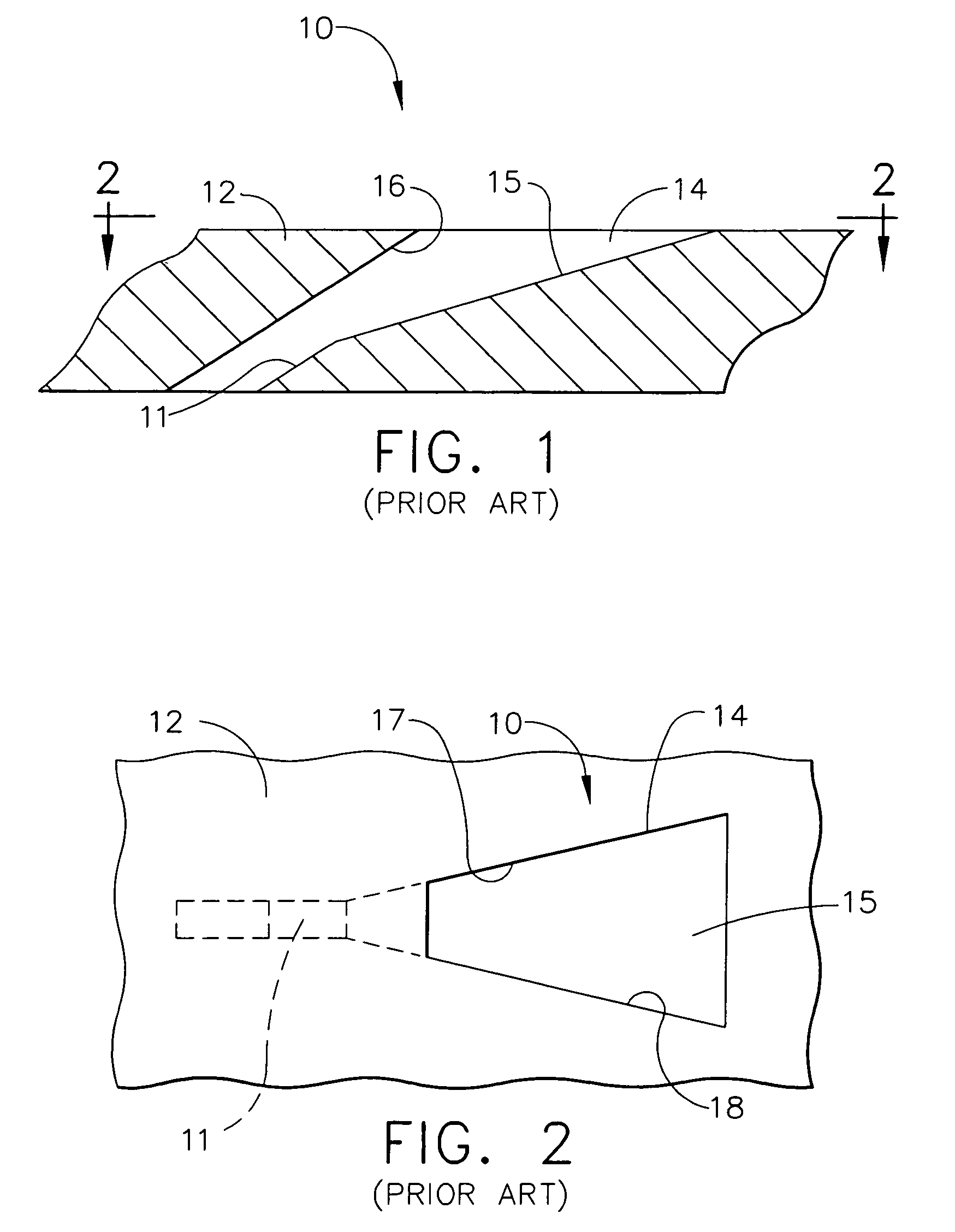
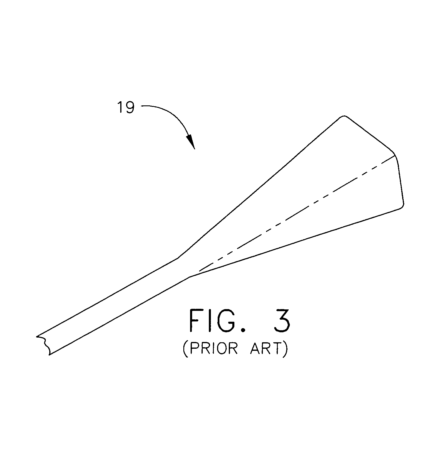
[0026]Referring now specifically to the drawings, FIGS. 1 and 2 illustrate a typical prior art cooling hole 10. The cooling hole 10 has a metering section 11 that communicates with a fluid circuit, not shown, in an airfoil 12. A diffuser section 14 communicates with the exterior surface of the airfoil 12. As shown in FIG. 1, the bottom wall 15 of the diffuser section 14 is straight as it diverges from the opposite, top wall 16, which is also straight. Similarly, as is shown in FIG. 2, the sidewalls 17 and 18 are likewise straight-sided as they diverge from the metering section 11 to the exterior surface of the airfoil 12. This is further illustrated in FIG. 3, where an Electrode Discharge Machining (EDM) tool 19 used to form the cooling hole 10 is shown.

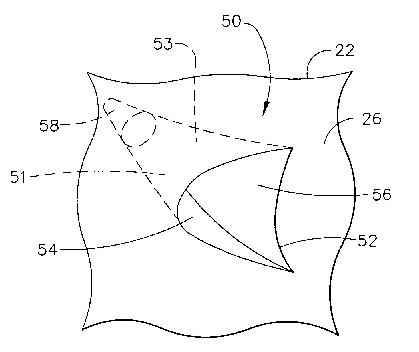
[0027]Referring now to FIG. 4, a turbine rotor blade 20 in accordance with an exemplary embodiment of the present invention is shown. The blade 20 includes an airfoil 22 having an integral dovetail 24 at a radially inner end for moun...


PUM


Abstract

A turbine airfoil a plurality of cooling holes formed in the external surface of the airfoil in fluid communication with a cooling circuit. The cooling holes have a metering section and a diffuser section opening to the external surface of the airfoil. The diffuser section has top, bottom and opposed side walls, where at least the opposed side walls and one or the other of the top and bottom walls of the diffuser section have a downstream diverging, bell-shaped configuration for achieving a flow of the cooling film from the cooling circuit with enhanced spread, enhanced attachment and less turbulence to a downstream surface of the airfoil local to each respective cooling hole.

Description

TECHNICAL FIELD AND BACKGROUND OF THE INVENTION[0001]This invention relates to a turbine airfoil that includes high efficiency, bell-shaped cooling holes. The bell-shaped holes are best suited for use on the suction side of the airfoil and the flat wall portion of the pressure side near the trailing edge. In a gas turbine engine, air is compressed in a compressor, mixed with fuel and ignited in a combustor for generating hot combustion gases which flow downstream through one or more stages of turbine nozzles and blades. The nozzles include stationary vanes followed in turn by a corresponding row of turbine rotor blades attached to the perimeter of a rotating disk. The vanes and blades have correspondingly configured airfoils which are hollow and include various cooling circuits and features which receive a portion of air bled from the compressor for providing cooling against the heat from the combustion gases.[0002]The turbine vane and blade cooling art discloses various configurati...

Claims


Application Information

Patent Timeline
Patent Type & Authority Patents(United States)
IPC IPC(8): F01D5/18
CPCF01D5/18F01D5/186Y02T50/673Y02T50/676F05D2250/26F05D2260/202F05D2250/20F05D2200/24F05D2250/292Y02T50/60
Inventor LEE, CHING-PANG
Owner GENERAL ELECTRIC CO
Why Eureka
Try Eureka