Usage monitoring apparatus

a monitoring device and monitoring device technology, applied in the direction of registering/indicating the working of machines, transmission systems, emergency protective arrangements for limiting excess voltage/current, etc., can solve the problems of multiple separate monitoring devices connected, unable to meet the needs of simple etis, and creating potential installation problems

Inactive Publication Date: 2008-07-15
OXLEY DEV
View PDF16 Cites 48 Cited by
  • Summary
  • Abstract
  • Description
  • Claims
  • Application Information

AI Technical Summary

Problems solved by technology

Such simple ETIs are not well suited where multiple separate electrical devices or electrical sub-systems all require monitoring.
Connection of the multiple separate monitoring devices could still prove problematic in some contexts.
The requirement of such ETIs for an electrical connection to the supply of each device being monitored can be a drawback, giving rise to its own concerns over reliability (in safety critical systems, the possibility that the ETI might itself compromise reliability of the system being maintained is desirably to be avoided) and creating potential installation problems, particularly where the usage monitoring system is to be “retro fitted” to an existing piece of equipment.

Method used


Image

  • Usage monitoring apparatus
  • Usage monitoring apparatus

Examples


Embodiment Construction

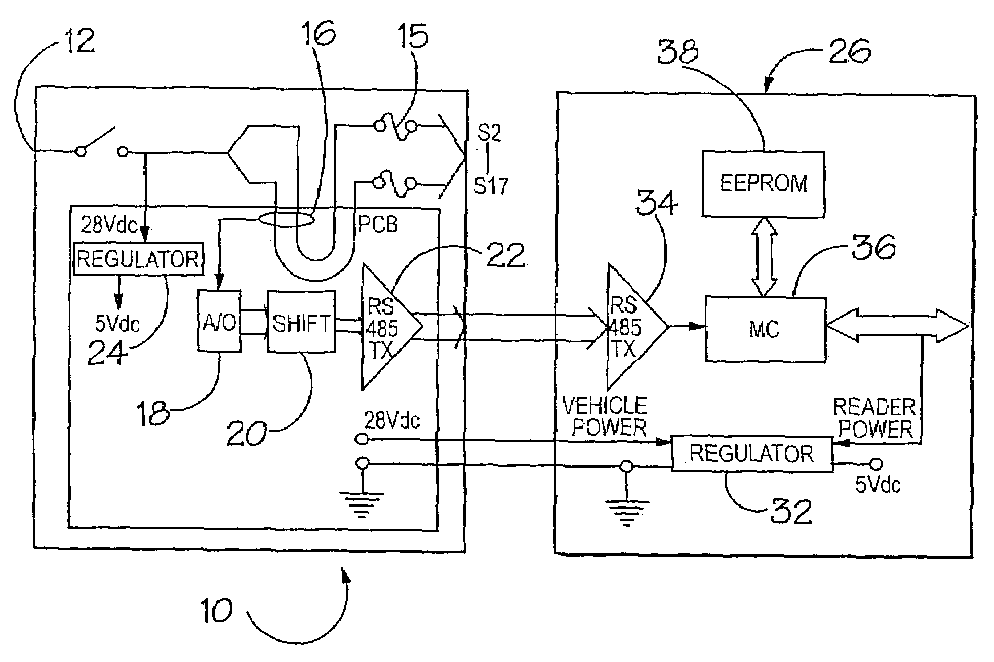
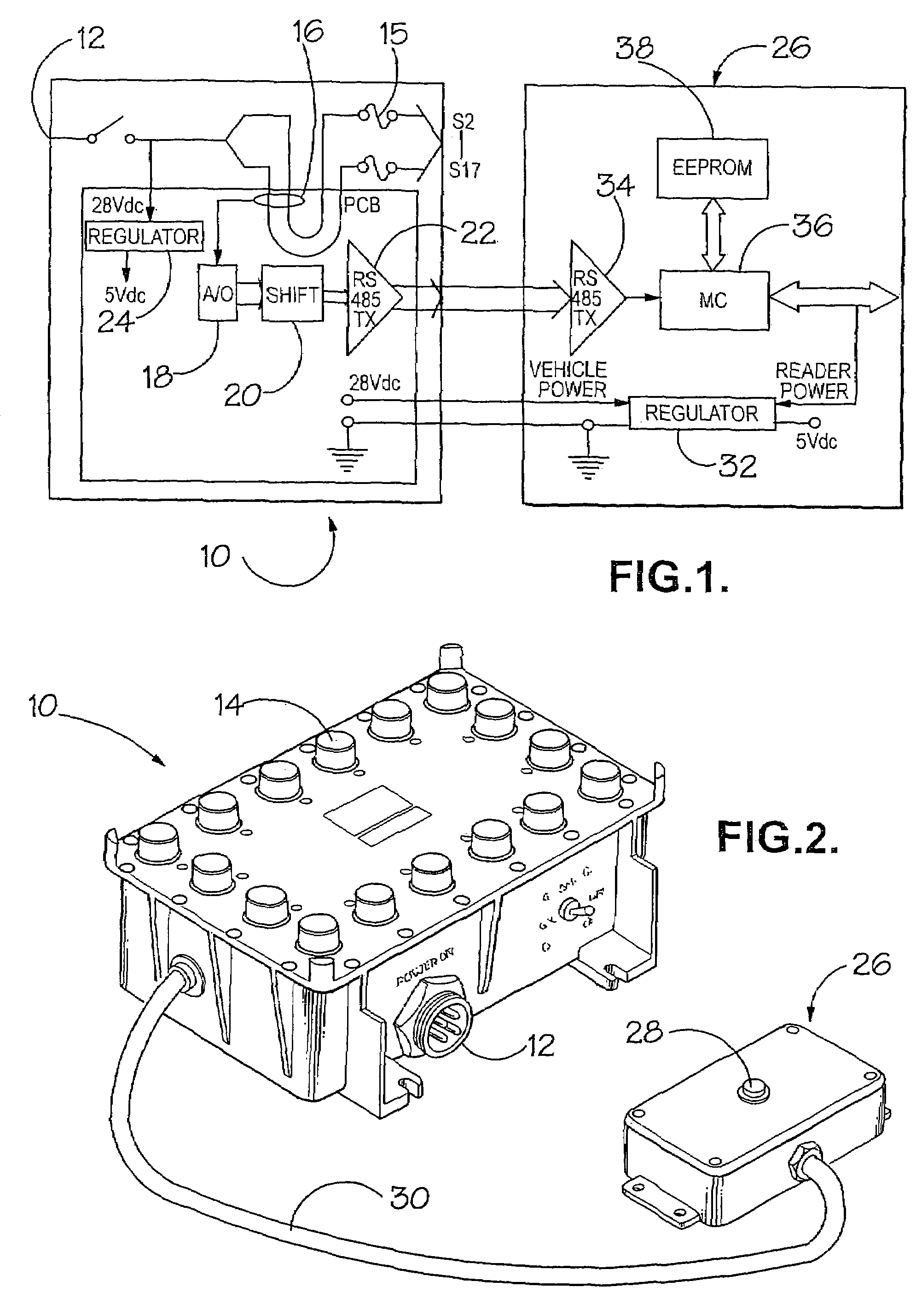
[0017]The illustrated system monitors usage of multiple electrical systems or sub-systems by monitoring current supplied to them from a common power distribution unit (PDU) 10. The present system is able to monitor sixteen systems. The illustrated PDU is used in a military vehicle. It connects to the vehicle power supply through a socket 12 and distributes power through lines S2 to S17 to various sub-systems of the vehicle's communications apparatus. The PDU's conventional purpose is to provide each sub-system with protection against excess current and the illustrated device provides this function through conventional excess current trip circuitry 15 with associated indicator lamps 14 at the PDU's exterior.

[0018]Also mounted within the PDU, in one embodiment, are non-invasive current monitoring devices such as 16, each associated with a respective power supply S2-S17. Various types of non-invasive current monitoring devices are known in the art, and can be used for sensing alternati...


PUM


Abstract

An apparatus is disclosed for monitoring usage of multiple electrical devices. The apparatus comprises multiple non-invasive current sensors for sensing current in respective conductors associated with the electrical devices. Such conductors may for example be the electrical power supply leads to the devices. The apparatus further includes multiple analogue to digital conversion functions for digitizing the output from the respective current sensors. A microprocessor is arranged to receive the digitized current sensor and is programmed to create usage data relating to the respective electrical devices. Such usage data may include cumulative elapsed running time. The microprocessor has an associated memory in which the usage data is stored in association with corresponding data identifying the electrical devices. The system further includes an interface through which the usage and identifier data are extractable, to provide usage information for the respective electrical devices. The apparatus may be divided into two separate sub-systems connected through a bus and it is particularly preferred that a sub-system incorporating the current sensors is mounted to, or otherwise associated with, a power distribution unit.

Description

BACKGROUND OF THE INVENTION[0001]1. Field of the Invention[0002]The present invention relates to apparatus for monitoring usage of multiple electrical devices.[0003]2. Description of the Relevant Art[0004]Monitoring of usage of electrical equipment is often desirable to ensure that servicing or replacement is carried out at the proper time, and also for warranty purposes. Defense equipment, whose reliability may be safety critical, is an important case in point. Elapsed time indicators (ETIs) which connect electrically to the electrical supply of a piece of equipment and which contain an elapsed time counter, typically driven from the equipment's electrical supply, are in themselves well known. They may have an integral display or may, as exemplified in Oxley (Development) Co. Ltd's European Patent Application 00302679.6, have an interface for interrogation by a separate unit. The ETI described in that patent application monitors a single power supply, the elapsed time counter being...

Claims


Application Information

Patent Timeline
Patent Type & Authority Patents(United States)
IPC IPC(8): G01R33/04G07C3/04
CPCG07C3/04
Inventor LATHAM, CHRISTOPHER BRIAN TAYLORFOSTER, MICHAEL CRAIG
Owner OXLEY DEV
Why Eureka
Try Eureka