Debris collection system for a planer

a technology for a planer and a collection system, which is applied in the direction of hand planes, flat surfacing machines, metal-working apparatus, etc., can solve the problems of not being able to effectively mix the air flow with the shavings or chips, and the removal of shavings or chips from the cutting area of the planer

Inactive Publication Date: 2008-11-25
BLACK & DECKER INC
View PDF84 Cites 6 Cited by
  • Summary
  • Abstract
  • Description
  • Claims
  • Application Information

AI Technical Summary

Problems solved by technology

One problem is the removal of the shavings or chips from the cutting area of the planer.
A second problem is the collection of the shavings or chips for disposal.
However, the problem with existing designs are that they are not efficient at mixing the air flow with the shavings or chips to entrain them for removal.
A problem with this design...

Method used


Image

  • Debris collection system for a planer
  • Debris collection system for a planer
  • Debris collection system for a planer

Examples


first embodiment

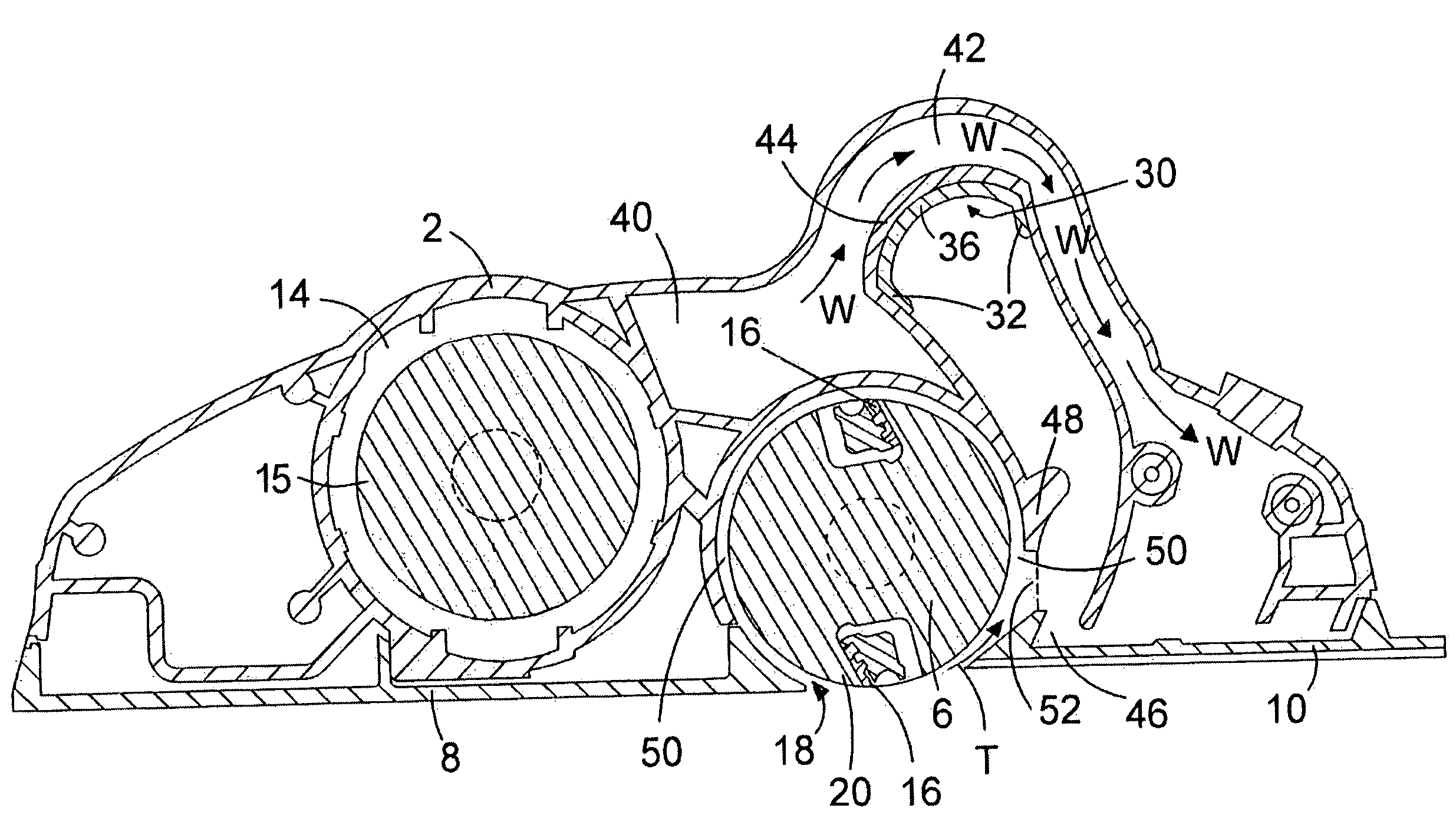
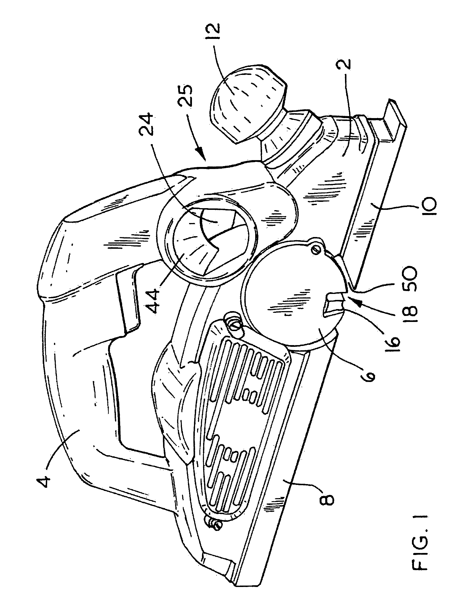
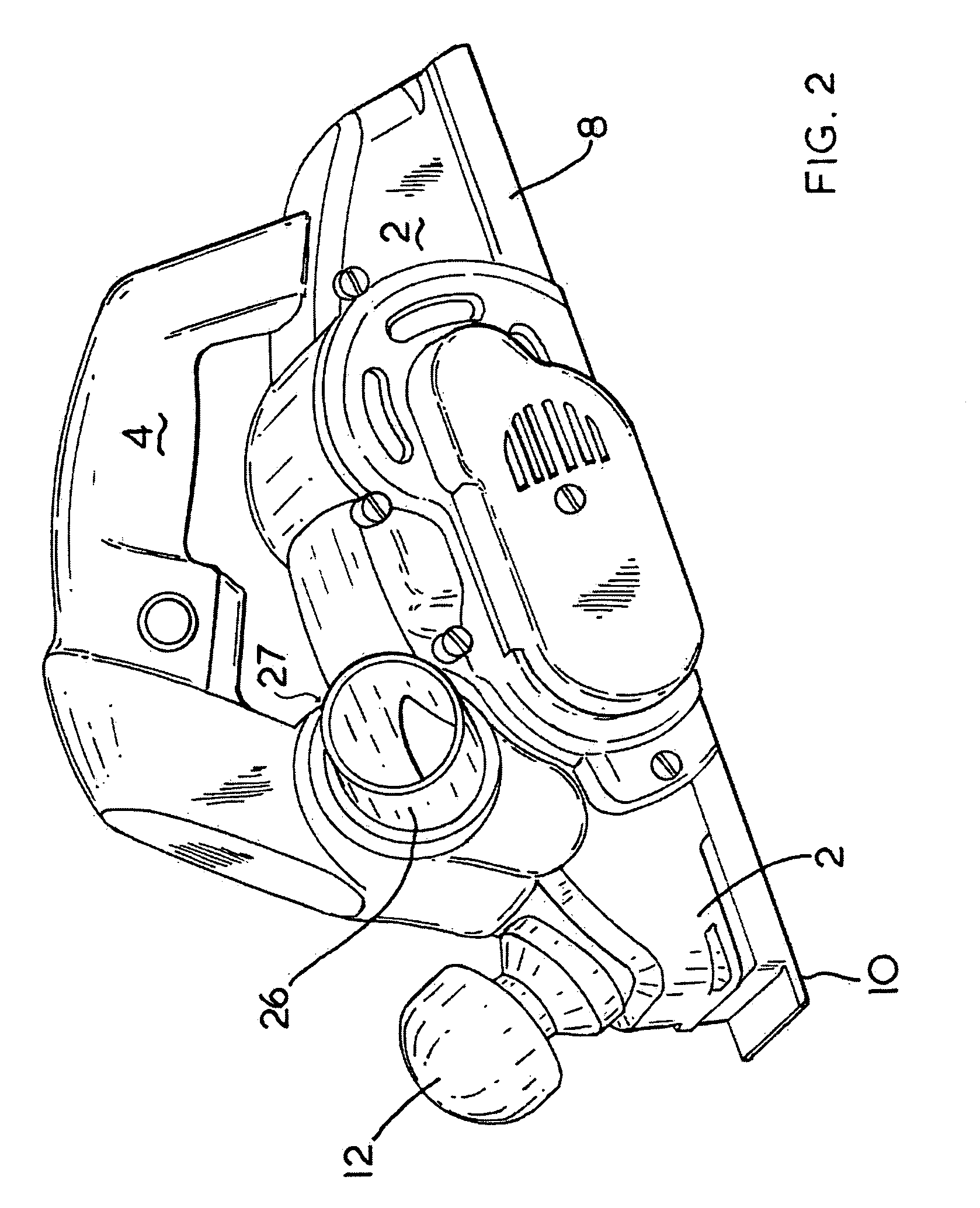
[0031]the planer will now be described with reference to FIG. 1 to 5. The planer comprises a body 2 having a handle 4 attached to the top of the body 2. A cutting drum 6 is rotatingly mounted within a recess 50 in the body 2 of the planer. The body 2 of the planer is mounted on a shoe formed from two pieces 8, 10. The rear part 8 is mounted rearwardly of the drum 6. The forward part 10 is mounted forward of the drum 6. An aperture 18 in the shoe is formed by the front 10 and rear sections of the shoe through which part of the periphery 20 of the cutting drum 6 extends. The height of the forward part 10 of the shoe can be adjusted in relation to the body 2 by the rotation of a knob 12 mounted on the front of the body 2 of the planer. The operation of the knob 12 is well known and will not therefore be discussed any further.

[0032]Mounted within cavity 14 of the body 2 of the planer is an electric motor 15 (shown schematically). The electric motor 15 rotatingly drives the cutting drum ...

second embodiment

[0039]Because the deflector 26 is angled downwardly by the angle 35 of the rib 38 being non perpendicular to the longitudinal axis 33 of the deflector, a large cavity is formed above the deflector 26 allowing air to easily pass over the top of the deflector 26. FIG. 15 shows a planer according to the The curve section 30 can be seen through the entrance of the aperture 24.

[0040]A third embodiment of the planer will now be described with reference to FIG. 16. Where the same features are shown in third embodiment are the same as those in the first, the same reference numbers have been used. The third embodiment is exactly the same as the first embodiment except that a vent or nozzle 56 has been added within the body above the area 46 in the body 2 forward of the wall 48 of the recess 50 in which the drum 6 is mounted. The nozzle 56 directs air into the path of the air with entrained debris at an acute angle approximately at the same height as the top of the expulsion aperture 52 form...


PUM


Abstract

A planer comprising: a body defining an exhaust aperture and including a wall, the wall defining a recess, a cutting drum rotatably mounted within the recess, a motor mounted within the body to rotatingly drive the cutting drum, the cutting action of the drum causing debris to be ejected from the recess; an airflow generator for producing an airflow within the body; a conduit defined within the body for directing the airflow, the conduit in communication with the exhaust aperture and connected to the recess for entraining and removing debris ejected from the recess; and a removable deflector having an inner end and an outer end, the deflector insertable through the exhaust aperture and connectable to the conduit for guiding the air flow and debris to outside of the body, and wherein the deflector is insertable at a downward slope from the outer end to the inner end.

Description

[0001]The present invention relates to a planer and in particular to debris collection containers for a planer and airflow and chip removal in a planer.BACKGROUND OF THE INVENTION[0002]Planers comprise a body mounted on a shoe. A rotatable cutting drum is mounted within the body which is rotatingly driven by an electric motor also mounted within the body. An aperture is formed through the shoe through which part of the periphery of the cutting drum extends. Cutting blades are mounted on the drum which, as the drum rotates, periodically pass through the aperture and below the shoe. In use, the shoe is located on a work piece and the drum is rotatingly driven by the motor. When the blades pass through the aperture and move below the shoe, the blades engage with the workpiece and remove a thin slice of the workpiece from the surface of the workpiece, producing shavings or chips. Due to the rotational movement of the drum, the shavings or chips are thrown in a generally forward and upwa...

Claims


Application Information

Patent Timeline
IPC IPC(8): B27C1/10B23Q11/00
CPCB23Q11/005B23Q11/0057B27C1/10
Inventor THOMAS, ROGER
Owner BLACK & DECKER INC
Why Eureka
Try Eureka