Hobble turning method and preferred applications for said method

a turning method and rotary technology, applied in the direction of turning apparatus, geometric arrangement, programme control, etc., can solve the problems of affecting the accuracy of the turning method, the difficulty of adjusting the rotary speed, so as to achieve the effect of reducing costs and ensuring accuracy

Inactive Publication Date: 2009-04-07
HOERMANSDOERFER GERD
View PDF41 Cites 8 Cited by
  • Summary
  • Abstract
  • Description
  • Claims
  • Application Information

AI Technical Summary

Benefits of technology

[0010]Therefore, the task at hand was to create a method for lathing workpieces with irregular, discontinuous or abruptly changing contours which on the one hand makes use of the existing possibilities of a machine with compound slide and NC control, as well as in connection with additional equipment such as linear slides. On the other hand it should overcome inertial problems and at the same time provide the option of extending the degrees of freedom with respect to the discontinuity of the intended contour by at least one additional dimension. In so doing a further goal of the new method is to waive the need for the previously necessary milling operations as far as possible.
[0020]The examples described above are concerned with relatively harmonious non-circular items with a constant advance in the longitudinal axis with fixed and programmed pitch. It is easily possible to extend the programming described by the addition of auxiliary points in order to produce perfect contours. The method according to the invention can be extended considerably further because it enables extreme jump machining of the workpiece, also along the longitudinal axis.
[0026]The method described above for spindle programming is however only suitable for certain machines and NC controls which are compliant with state-of-the-art developments. In these machines the spindle is integrated in the drive motor whereby the entire unit can be addressed either as the turning axis or as the C axis. With correspondingly fast NC controls there is a certain degree of a equivalence with respect to programming between the speed of turning of the spindle, which is for example expressed in that the C axis can be used even at very high rpm (under certain circumstances several thousand rpm). This means that the programming of the C axis allows cutting speeds to be achieved which are comparable with those of standard lathing operations.
[0030]A further application is the inexpensive manufacture of so-called circular wedge profiles on the internal or external coupling faces of coupling elements in mechanical engineering.
[0042]In the case of a circular wedge coupling, and in contrast to cylindrical cross-pressure locks, the joint connecting areas of the shaft and the hub are not round but have so-called wedge surfaces on the circumference. Generally there are three wedge surfaces. They comprise identical and reciprocally opposed turned sections of spirals, e.g. logarithmic spirals. When clamping by turning through a certain relatively small angular amount (e.g. 15°) the necessary homogenous contact surface is achieved, and hence the maximum possible frictional connection between the shaft and the hub. Circular wedge coupling also provides for an excellent transfer of the respective forces and boast an advantageous rigidity of configuration. A coupling with three circular wedges on the circumference is self-centering. If the radial pitch of the wedges surfaces is selected between 1:50 and 1:200, circular wedge couplings are generally also self-locking.

Problems solved by technology

Despite this, there are certain limitations in connection with certain geometrical shapes or because of the time required.
If as a result of the geometry of a workpiece it is only possible to employ milling techniques, it is unavoidable that either a considerably longer machining time is involved or that a less uniform surface has to be accepted.
However, this notwithstanding, even milling techniques are subject to certain limitations as far as the geometry is concerned.
In the case of erosion the time requirement is also extremely long.
While it is also true that the cutting of non-circular contours has been possible for a number of years now using profiling turning devices available commercially, these devices are expensive and therefore require a corresponding scale of capital investment.
Furthermore such machines can only be connected to the initially intended interface and are limited to the specified contour with two-dimensional non-circular geometry.
In addition to the very complex and very sensitive mechanical configuration, this machine has extremely limited possibilities which in turn are themselves limited to the generation of two-dimensional non-circular geometries.
However, this technique only allows extremely small adjustments to be achieved.
While it would be technically possible, for example, to use a magneto-dynamic system to achieve considerably larger control movements, these would as previously be limited to a single movement axis.
In order to achieve specific three-dimensional discontinuous machining it would be necessary to add a second or possibly even a third orthogonally arranged movement unit to create a tool with complex directions of movement, whereby this would be of extremely complex design and demand highly sophisticated control electronics.
To date a tool of this design is not yet available.
This latter would be very difficult to achieve despite the reduced mass of the system.
There is no technique for moving the carriage along the Z-axis in jumps or with superimposed oscillation, for example.
However, a machine of this description would be limited in its possibilities to the intended and similar applications unless its basic kinematic method is modified.
Furthermore, a special machine of this description would be relatively expensive to acquire.

Method used


Image

  • Hobble turning method and preferred applications for said method
  • Hobble turning method and preferred applications for said method
  • Hobble turning method and preferred applications for said method

Examples


Embodiment Construction

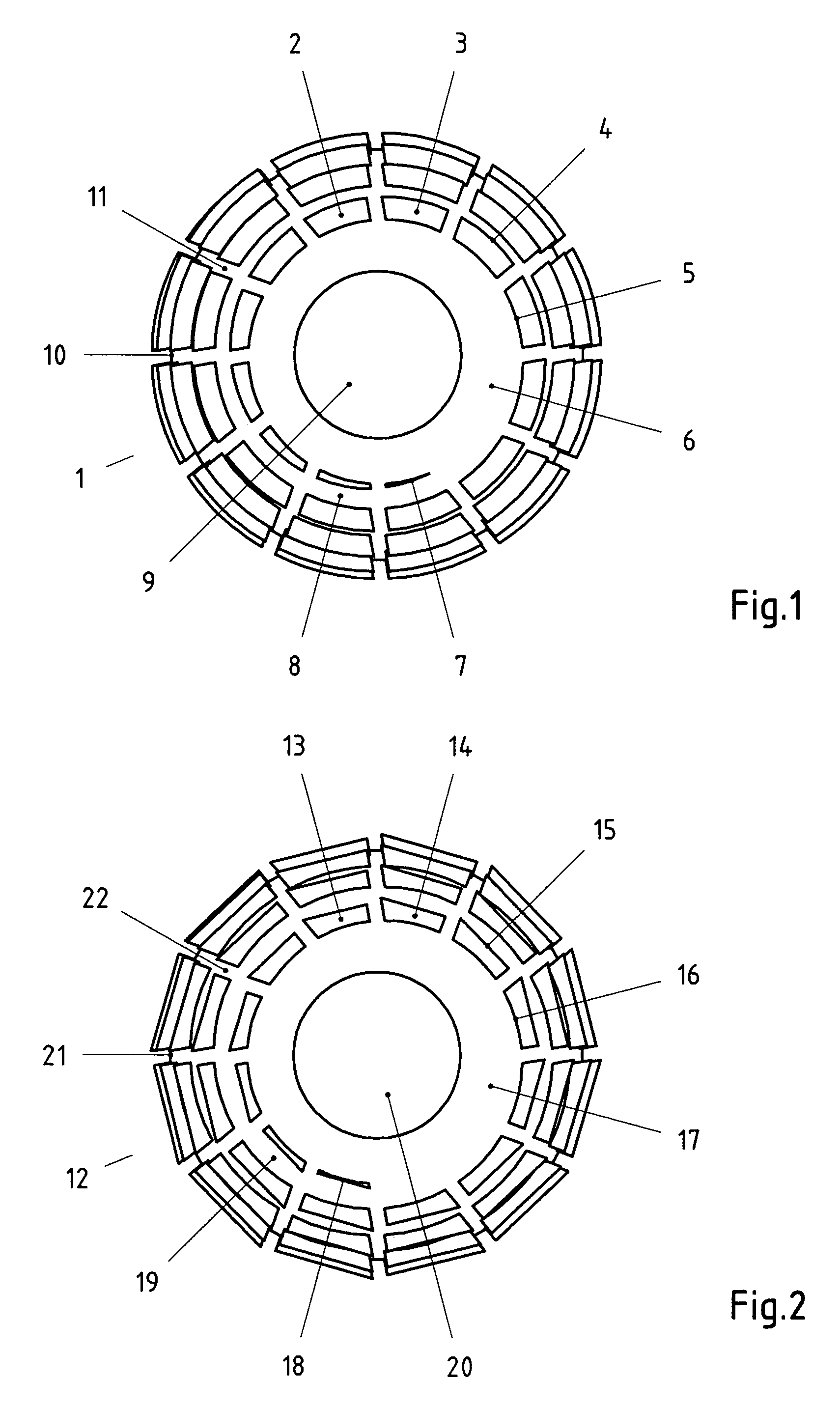
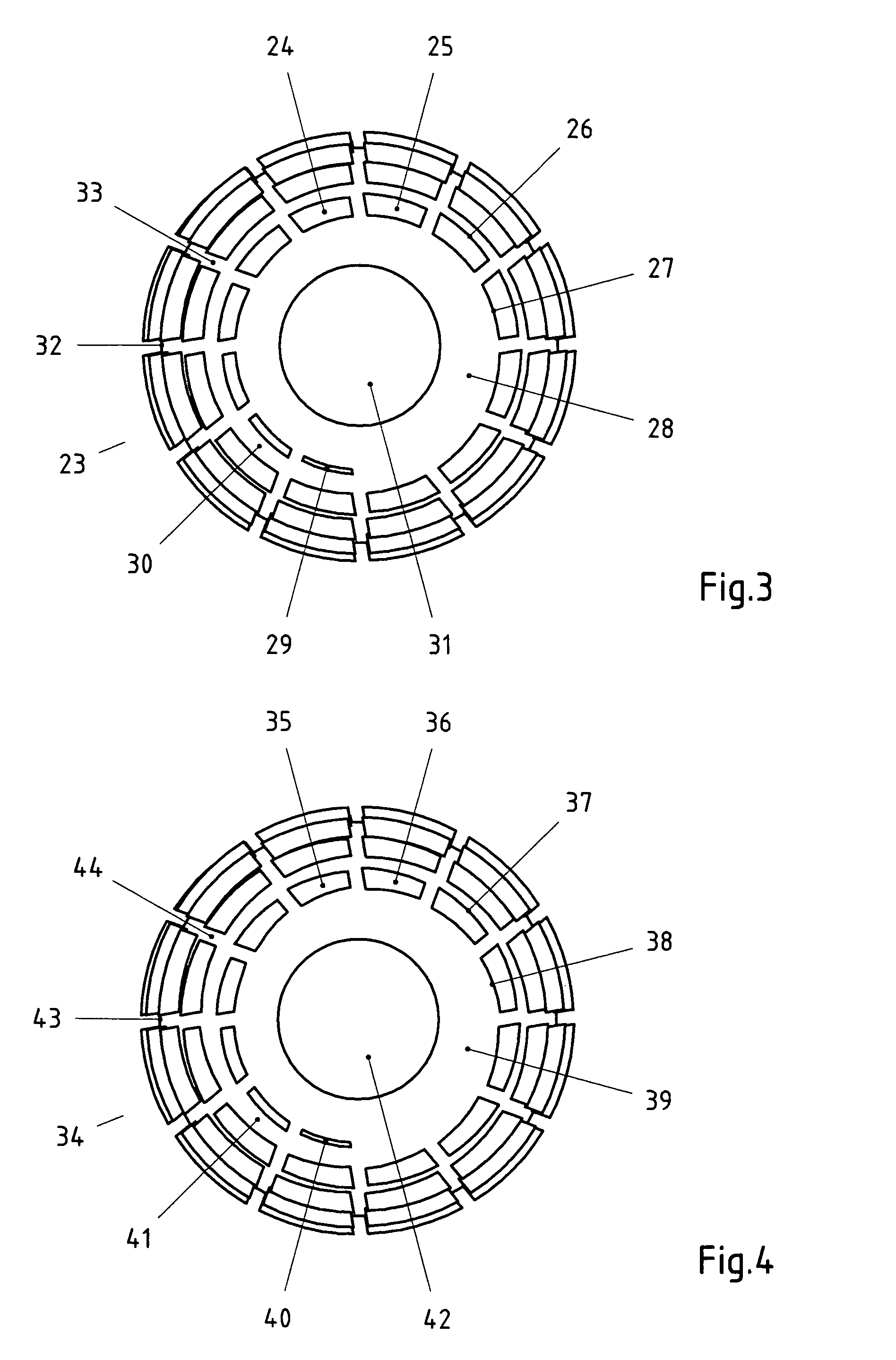
[0063]The drawing in FIG. 1 presents the pole-side view of a hemispherical screw-in type artificial hip joint socket 1 with a flat thread according to state-of-the-art based on an example with a 1.3 magnification. In the example the nominal diameter is 54 mm, the average tooth height is 2.6 mm, the pitch is 5 mm and the bottom hole diameter is 22 mm. These basic dimensions were selected for technical drawing reasons and are also retained in drawing FIGS. 2 through 4 to allow better comparability. Similarly, the windup angle of the tapping groove(s) has been set at 0° throughout in order to reduce the drawing work. It is known that a woundup tapping groove(s) offers advantages with respect to a more favorable cutting angle and a more evenly distributed transfer of forces.

[0064]A dome shaped thread-free area 6 on the shell body continues from the bottom hole 9 of the screw-in type artificial hip joint socket 1. In the drawing the diameter of the shell body is represented by the equato...


PUM

PropertyMeasurementUnit
diameteraaaaaaaaaa
diameteraaaaaaaaaa
heightaaaaaaaaaa

Abstract

A process for hobble lathing, and preferred process applications, for the cutting of workpieces with non-circular or discontinuous contours on programmable lathes. The use and combination of a special program e.g. of thread cycles and hobble values for the diameter and / or the longitudinal axis or the pitch, the angle of the spindle, in option of a reciprocal-step technique and interleaved machining sequences opens up virtually infinite possibilities. The preferred applications of the process allow special threads to be cut on screw-in bodies, e.g. screw-in artificial hip joint sockets and bone screws for example with neutral or virtually any angle of pitch or relief of the thread blade as well as e.g. internal and external contours on workpieces for circular wedge connections. A particularly beneficial hip joint socket is presented comprising so-called screw or threaded surfaces.

Description

CROSS-REFERENCE TO RELATED APPLICATIONS[0001]This application is a continuation of Ser. No. 09 / 605,261 filed Jun. 28, 2000 now abandoned, which is a continuation-in-part of PCT application Nos. PCT / EP98 / 08473 filed Dec. 12, 1998 and PCT / EP00 / 05325 filed Jun. 8, 2000.BACKGROUND OF THE INVENTION[0002]1. Field of the Invention[0003]This invention relates to a special method for the turning of workpieces and preferred applications of the method. The invention also concerns a screw-in type artificial hip joint socket designed for cement-less implantation in the human medical domain.[0004]2. Description of the Related Art[0005]The principle of conventional lathing is a method which has been known of for many years and is used for the cutting manufacture of workpieces, e.g. of wood, metal or plastic. In recent years, lathing technology has undergone rapid advance due to the introduction and continuous development of numerical controls. Thus, today it is absolutely no longer any problem to,...

Claims


Application Information

Patent Timeline
Patent Type & Authority Patents(United States)
IPC IPC(8): A61F2/32B23B1/00A61F2/30A61F2/34B23B5/18B23B5/44B23B5/46B23G1/00B23G1/02B23Q27/00G05B19/18G05B19/4093
CPCA61F2/34B23G1/00B23Q27/00A61F2/3094A61F2002/3085A61F2002/30858Y10T82/10Y10T82/2502A61F2002/30876A61F2002/30873
Inventor HOERMANSDOERFER, GERD
Owner HOERMANSDOERFER GERD
Why Eureka
Try Eureka