Implantable medical device with ventricular pacing protocol

a medical device and ventricular pacing technology, applied in electrotherapy, heart stimulators, therapy, etc., can solve the problem of so long delay of intravenous av

Active Publication Date: 2009-06-02
MEDTRONIC INC
View PDF117 Cites 5 Cited by
  • Summary
  • Abstract
  • Description
  • Claims
  • Application Information

AI Technical Summary

Problems solved by technology

The difficulty in facilitating this preference is that in a great many patients, the intrinsic AV delay is so long that traditional DDD timing will almost always deliver a ventricular pacing pulse.

Method used


Image

  • Implantable medical device with ventricular pacing protocol
  • Implantable medical device with ventricular pacing protocol
  • Implantable medical device with ventricular pacing protocol

Examples


Embodiment Construction

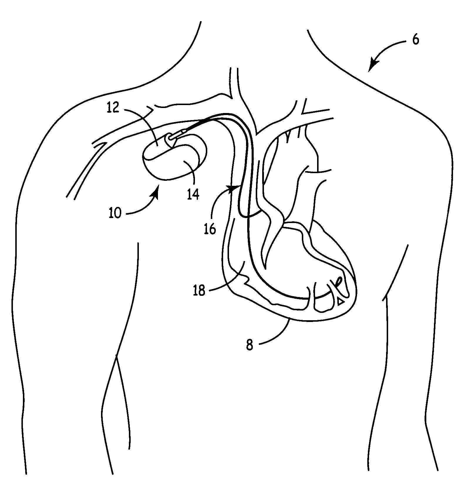
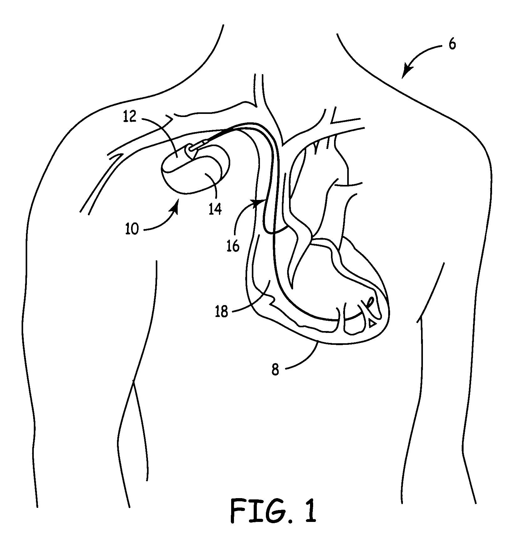
[0033]FIG. 1 is a simplified schematic view of one embodiment of implantable medical device (“IMD”) 10 of the present invention implanted within a human body 6. IMD 10 comprises hermetically sealed enclosure 14 and connector module 12 for coupling IMD 10 to pacing and sensing leads 16 and 18 within heart 8.

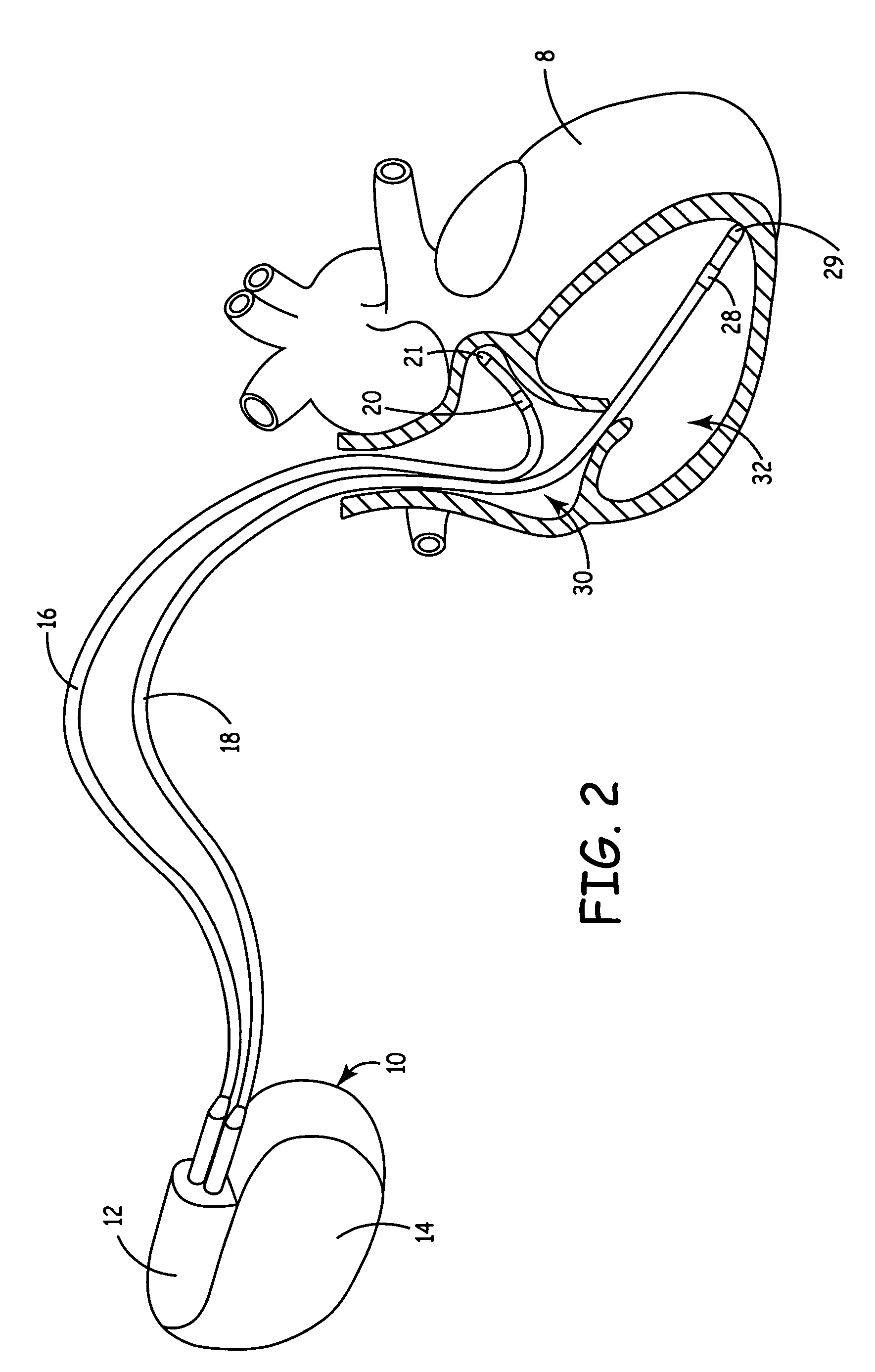
[0034]FIG. 2 shows atrial and ventricular pacing leads 16 and 18 extending from connector module 12 to the right atrium 30 and right ventricle 32, respectively, of heart 8. Atrial electrodes 20 and 21 disposed at the distal end of atrial pacing lead 16 are located in the right atrium 30. Ventricular electrodes 28 and 29 at the distal end of ventricular pacing lead 18 are located in the right ventricle 32.

[0035]FIG. 3 is a block diagram illustrating the constituent components of IMD 10 in accordance with one embodiment of the present invention, where IMD 10 is pacemaker having a microprocessor-based architecture. IMD 10 is shown as including activity sensor or accelerometer 11, whi...


PUM


Abstract

An implantable medical device operates to promote intrinsic ventricular depolarization according to a pacing protocol. The medical device determines a course of action based upon the presence or absence of sensed ventricular activity. The device further determines whether that activity is properly conducted or the result of a PVC or nodal rhythm.

Description

FIELD OF THE INVENTION[0001]This invention relates implantable medical devices and more particularly to implantable medical device for cardiac pacing.BACKGROUND OF THE INVENTION[0002]While a variety of pacing modes are available, dual chamber pacing / sensing (DDD) is commonly utilized. With a DDD mode, atrial and ventricular events are both sensed. If an expected intrinsic event is not sensed within a predetermined time window, an appropriate atrial or ventricular pacing stimulus is delivered. This mode provides a great deal of control over the patient's cardiac rhythm and the timing (e.g., the atrial-ventricular or AV delay) may be modified based upon many different factors. One of the many benefits provided by the DDD mode is the ability to maintain AV synchrony. That is, for any given atrial event there will be a corresponding ventricular event, either intrinsic or paced.[0003]Another beneficial feature is rate responsive (RR) pacing. With rate responsive pacing, a demand sensor i...

Claims


Application Information

Patent Timeline
Patent Type & Authority Patents(United States)
IPC IPC(8): A61N1/00
CPCA61N1/368A61N1/3622A61N1/3688
Inventor STOOP, GUSTAAF A. P.BOUTE, WILLEMVAN DAM, PETER M.ROUW, MATTIAS
Owner MEDTRONIC INC
Why Eureka
Try Eureka