Obstacle detector for vehicle

a technology for obstacles and detectors, applied in the field of obstacles detectors for vehicles, can solve the problems of difficult miniaturization of each, high cost, and unsuitability for recognizing the position and direction of obstacles, and achieve the effect of improving the accuracy of obstacle detection

Active Publication Date: 2009-07-07
CLARION CO LTD
View PDF19 Cites 16 Cited by
  • Summary
  • Abstract
  • Description
  • Claims
  • Application Information

AI Technical Summary

Benefits of technology

[0015]According to this construction, the photographed images are converted into overhead images to carry out the obstacle detection. Therefore it is possible to eliminate the effects caused by distortion of a lens of the camera and / or position adjustment of the camera, so that the obstacle detection accuracy is improved.
[0016]According to an embodiment of the present invention, the controller is configured to utilize two image-frames with a long-time interval to carry out the second obstacle detection when the vehicle runs at a low speed, and utilize two image-frames with a short-time interval to carry out the second obstacle detection when the vehicle runs at a high speed.
[0017]According to this construction, the intervals of the image-frames to be compared are changed in accordance with the vehicle speed. Therefore, due to this operation, it is possible to improve the obstacle detection accuracy when the vehicle runs at the low speed with a few image variations between image-frames.
[0019]According to this construction, a conversion table in accordance with the posture of the vehicle is utilized when the photographed image is converted into the overhead image. This operation may eliminate the effects on variations of the photographed images resulting from variations of the vehicle posture; therefore, it is possible to improve the obstacle detection accuracy.
[0030]According to this construction, it is possible to visually draw attention of the driver.
[0031]According to the present invention, it is possible to provide an obstacle detector for a vehicle which detects the obstacle based on the images converted into the overhead images of the vehicle surroundings, and divides the area in the vehicle surroundings where the obstacle is to be detected into a plurality of regions, and properly utilizes a plurality of obstacle detection methods in accordance with the divided regions and running status of the vehicle, to improve the obstacle detection accuracy.

Problems solved by technology

However, since the lazar radar includes a drive mechanism for scanning the lazar, and the millimeter-wave lazar includes a transmitting and receiving antenna, it is difficult to miniaturize each of them.
In addition, they are highly expensive.
Further, although the supersonic is inexpensive, its resolution in the lateral direction is low and may only detect whether there is an object or not, therefore, it is unsuitable for recognizing the position and direction of the obstacle.
Additionally, if the device which detects the obstacle according to the differences of the images between the image-frames of the camera image is used, when the vehicle runs at a low speed, there is nearly no difference in images between the two successive image-frames, so there is a problem that the detection accuracy decreases.
Moreover, in the stereo camera device, there is a problem that the calculation accuracy of the differences between the right and left images gets worse, due to distortion of the lens of the camera, and the detection accuracy of the obstacle decreases.
In addition, when the devices are attached to the vehicle, it is necessary to adjust the attachment for every vehicle with high accuracy, so that a large amount of labor is required.

Method used


Image

  • Obstacle detector for vehicle
  • Obstacle detector for vehicle
  • Obstacle detector for vehicle

Examples


Embodiment Construction

[0047]Preferred embodiments of the present invention will be explained below by referring to the accompanying drawings. The scope of the invention, however, is not limited to these embodiments. Within the scope of the present invention, any structure and material can be appropriately modified.

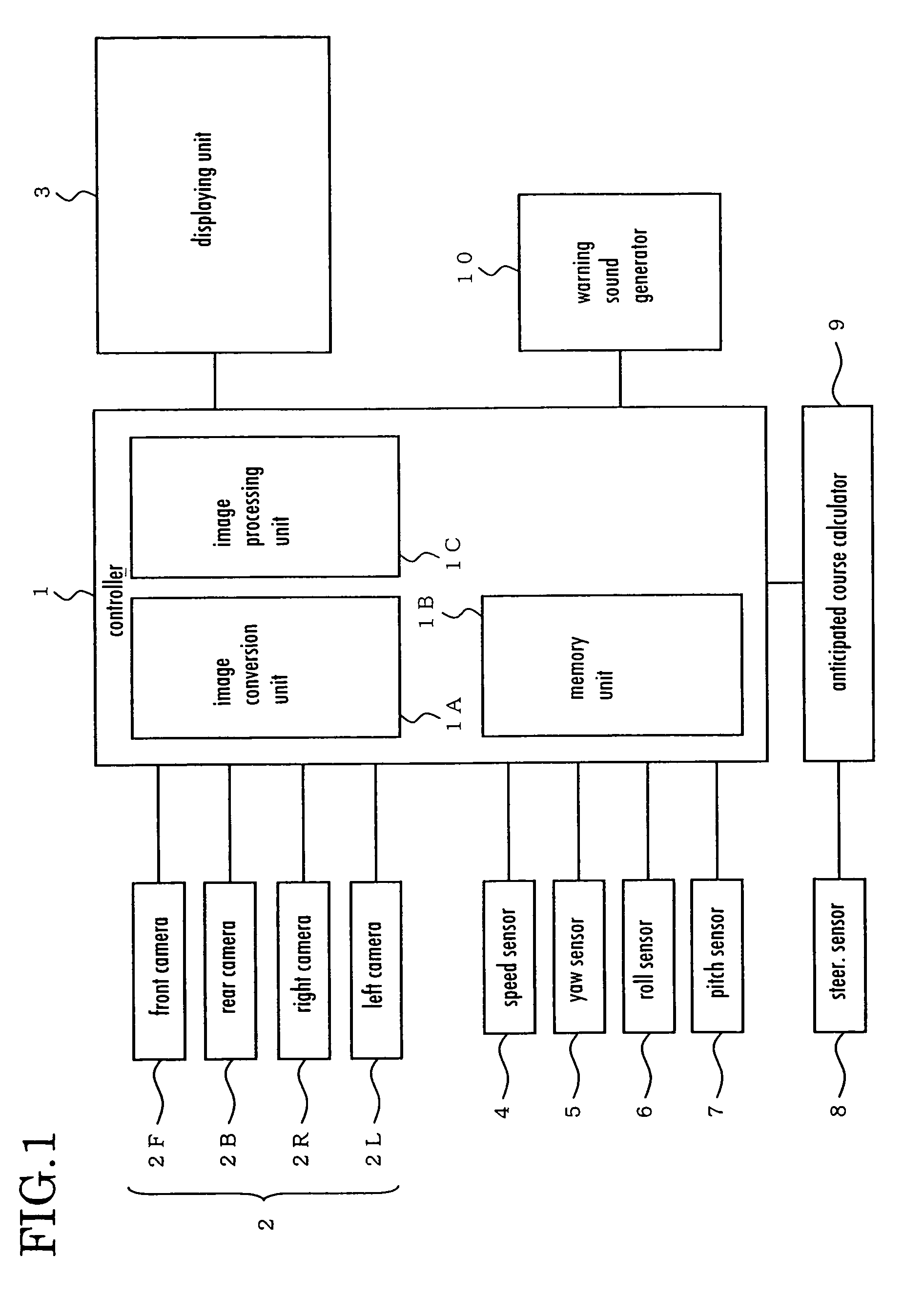
[0048]FIG. 1 shows a block diagram of a preferred embodiment of the present invention.

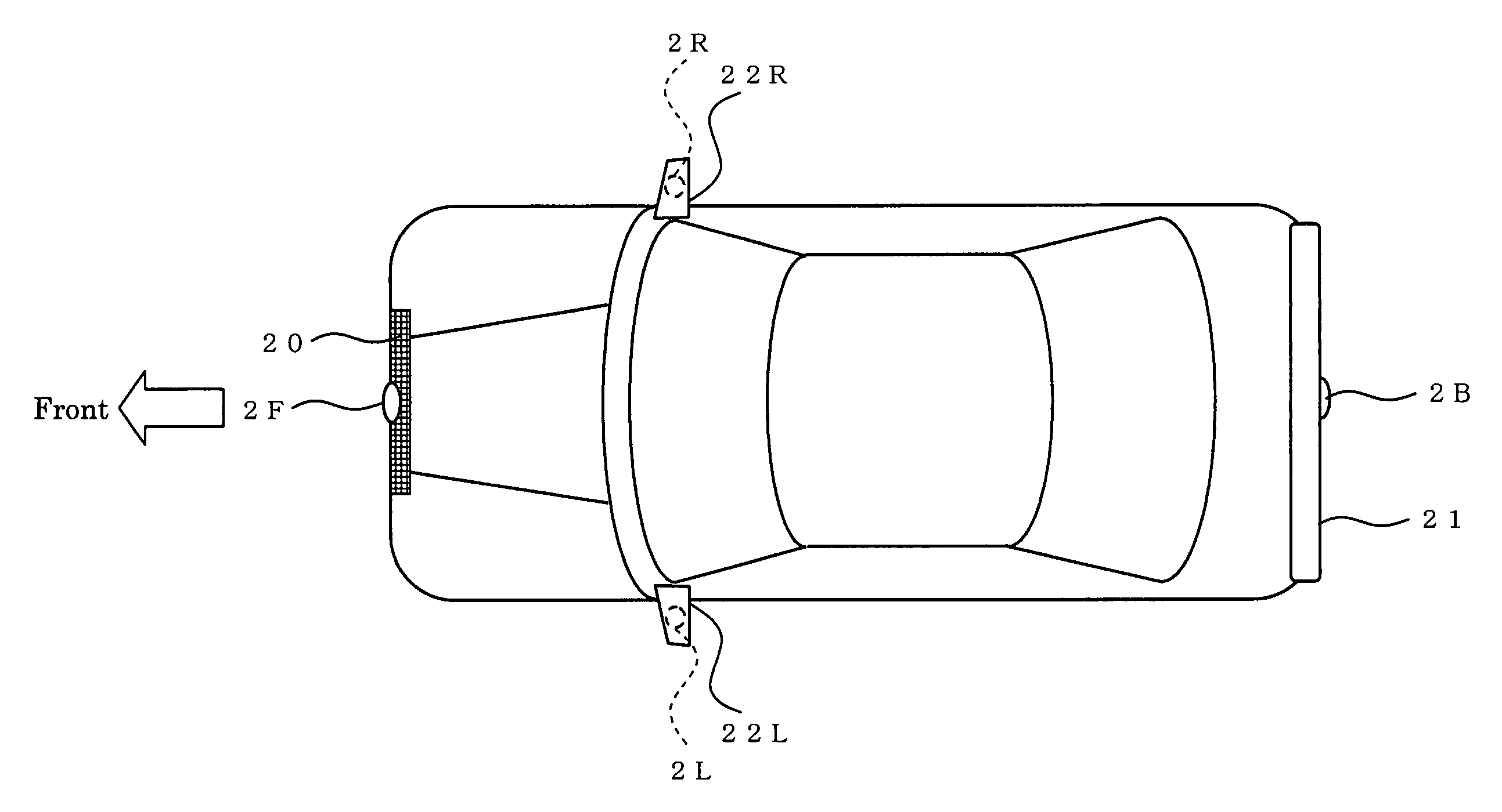
[0049]A controller 1 is electrically connected with photographing camera units 2 and takes image signals output from the photographing camera units 2. The photographing camera units 2 include a front photographing camera 2F, a rear photographing camera 2B, a right-side photographing camera 2R and a left-side photographing camera 2L. The photographing camera units 2 correspond and structure a plurality of photographing units according to the present embodiment of the invention.

[0050]The controller 1 is equipped with an image conversion unit 1A for converting a taken image into an overhead image and / or a predete...


PUM


Abstract

An obstacle detector used for a vehicle includes: a plurality of photographing units configured to photograph scenes in vehicle surroundings; and a controller configured to carry out a first obstacle detection that detects an obstacle in the vehicle surroundings based on images photographed by at least two photographing units of the plurality of photographing units, and a second obstacle detection that detects the obstacle in the vehicle surroundings based on two image-frames photographed by at least one photographing unit of the plurality of photographing units, wherein the controller is configured to carry out at least the first obstacle detection in a region, photographed by the at least two photographing units, and carry out the second obstacle detection in a region photographed by the at least one photographing unit, of a photographed range photographed by the plurality of photographing units.

Description

BACKGROUND OF THE INVENTION[0001]1. Field of the Invention[0002]The present invention relates to an obstacle detector for a vehicle.[0003]2. Description of the Related Art[0004]Devices for detecting obstacles surrounding a vehicle have been in practical use today. The obstacle detectors for a vehicle may be divided broadly into two kinds, i.e., the detector utilizing a radar principle to detect the obstacles, and the detector utilizing cameras to detect the obstacles.[0005]Usually, the obstacle detector for a vehicle utilizing the radar principle includes the following types, namely, lazar radar which transmits radar light and detects a position of an obstacle according to the arrival time of the lazar light reflected by the obstacle (for reference, see JP-H05-119147 A), millimeter-wave radar which transmits millimeter-wave in the GHz band and detects a position of an obstacle based on the arrival time of the millimeter-wave reflected by the obstacle (for reference, see JP-H05-27333...

Claims


Application Information

Patent Timeline
Patent Type & Authority Patents(United States)
IPC IPC(8): B60Q1/00
CPCG01S11/12
Inventor IWAMA, TAKAAKI
Owner CLARION CO LTD
Why Eureka
Try Eureka