Fundus observation device

a technology of observation device and camera, which is applied in the field offundus observation device, can solve the problems of image quality deterioration, image may not be captured, and it is not easy to fix the ey

Active Publication Date: 2009-07-28
KK TOPCON
View PDF14 Cites 9 Cited by
  • Summary
  • Abstract
  • Description
  • Claims
  • Application Information

AI Technical Summary

Benefits of technology

[0041]The present invention is intended to solve the abovementioned problems, with the purpose of providing a fundus observation device capable of easily capturing an image at the desired position on a fundus oculi.

Problems solved by technology

When scanning the peripheral region of a fundus oculi with signal light by an optical image measuring device, shading of signal light due to the iris of the eye or the like may occur and thereby the quality of the image may deteriorate, and at worst, an image may not be captured.
However, it is not easy to fixate the eye such that the desired position on the fundus oculi is arranged close to the optical axis of the optical system.
Consequently, it is not easy to capture an image at the desired position on the fundus oculi.

Method used


Image

  • Fundus observation device
  • Fundus observation device
  • Fundus observation device

Examples


modified example

[0188]The configuration described above is merely one example to preferably implement the fundus observation device related to the present invention. Therefore, optional modifications may be implemented appropriately within the scope of the present invention.

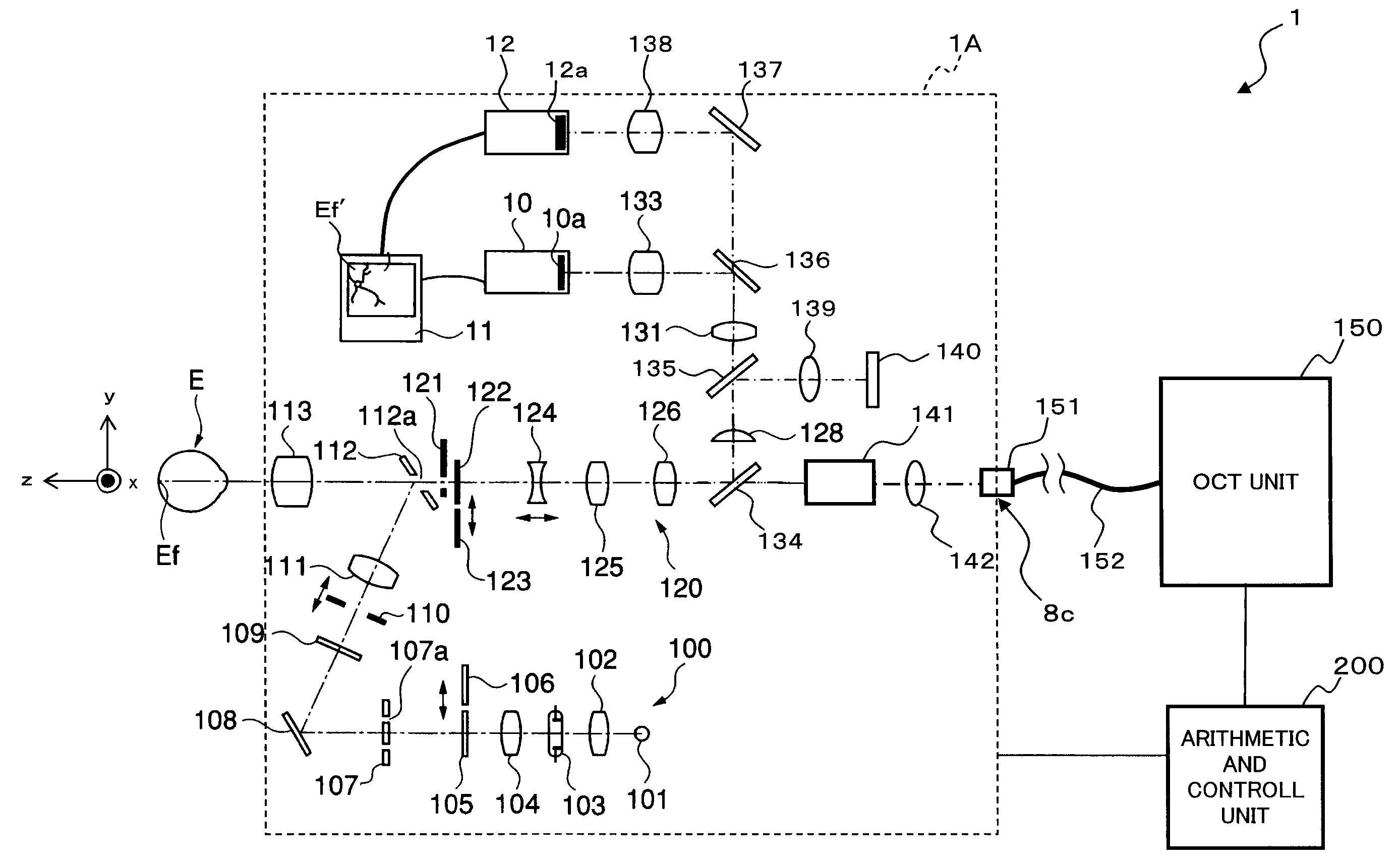
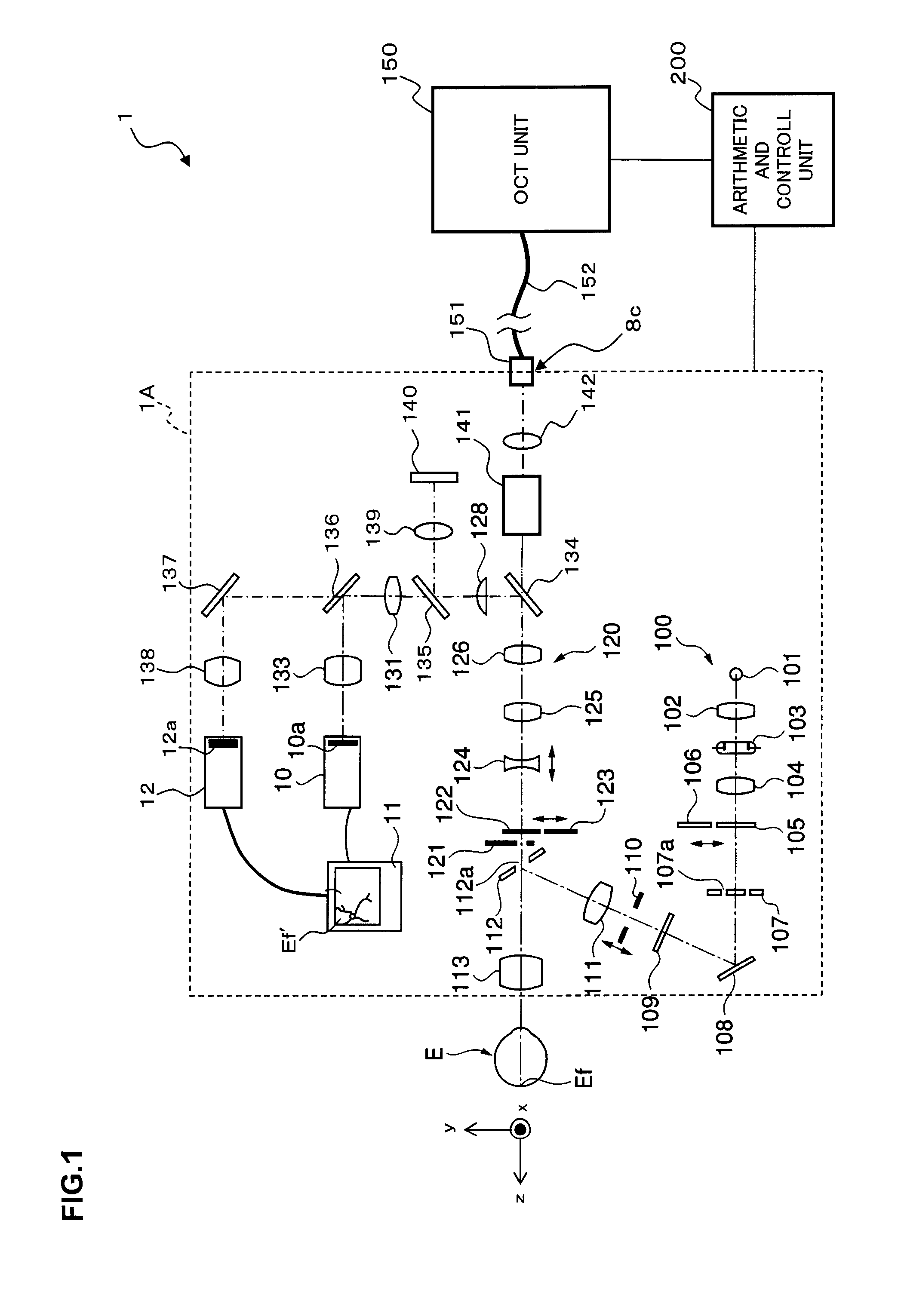
[0189]Although the above fundus observation device 1 is configured so as to be capable of projecting the internal fixation target onto the fixation position for the center of the fundus oculi, the fixation position for macula area, and the fixation position for optic papilla on the fundus oculi Ef, it is sufficient to configure the fundus observation device related to the present invention to be capable of projecting the internal fixation target onto at least one of these fixation positions.

[0190]In addition, in the switching operation of the projection position of the internal fixation target, it is sufficient to be capable of switching the projection position of the internal fixation target to two fixation positions of these.

[...


PUM


Abstract

LCD 140 is provided for displaying an internal fixation target for fixating an eye E. Projection optical system (a part of an imaging optical system 120) is provided for projecting the displayed internal fixation target onto the a fundus oculi Ef. Image forming part 220 is provided for forming 2-dimensional images (images of fundus oculi) Ef of the surface of fundus oculi Ef. Display part 240A is provided for displaying images of fundus oculi Ef. Operation part 240B is provided for specifying the position of the displayed images of fundus oculi Ef. Main controller 211 is provided for changing the projection position of the internal fixation target on the fundus oculi by changing the display position of the fixation target by the LCD 140 based on the specified position. The image forming part 220 forms tomographic images of the fundus oculi Ef with the internal fixation target projected.

Description

BACKGROUND OF THE INVENTION[0001]1. Field of the Invention[0002]The present invention relates to a fundus observation device, for observing the state of the fundus oculi of an eye.[0003]2. Description of the Related Art[0004]As a fundus observation device, conventionally a fundus camera has been widely used. FIG. 11 shows one example of the appearance of a conventional fundus camera in general, and FIG. 12 shows one example of an optical system composition to be internally accommodated therein (e.g. JP Patent laid-open No. 2004-350849). Furthermore, “observation” is intended to include at least a case in which produced fundus images are observed (fundus observations with the naked eye may be included).[0005]First, referring to FIG. 11, an explanation is made regarding the appearance of a conventional fundus camera 1000. This fundus camera 1000 is provided with a platform 3 mounted on a base 2 slidably in the front and rear, right and left (horizontal direction) directions. On this p...

Claims


Application Information

Patent Timeline
Patent Type & Authority Patents(United States)
IPC IPC(8): A61B3/10
CPCA61B3/102
Inventor FUKUMA, YASUFUMIOTSUKA, HIROYUKIYUMIKAKE, KAZUHIKOOKADA, HIROAKINISHIO, YUTAKA
Owner KK TOPCON
Why Eureka
Try Eureka