Linear friction welding apparatus and method

a welding apparatus and friction welding technology, applied in the field of linear friction welding, can solve the problems of substantial disadvantages of linear friction welding processes utilizing a single forge axis to achieve welds, and achieve the effects of minimal component distortion, improved welding process control, and high strength

Active Publication Date: 2009-12-01
CYRIL BATH
View PDF32 Cites 16 Cited by
  • Summary
  • Abstract
  • Description
  • Claims
  • Application Information

AI Technical Summary

Benefits of technology

[0011]It is another object of the invention to provide linear friction welding apparatus and methods for producing high strength welds with minimal component distortion.
[0012]It is a further object of the invention to provide linear friction welding apparatus and methods for improving control of the welding process.
[0013]It is a further object of the invention to provide apparatus and methods that expand the capabilities of a linear friction welding machine.
[0014]It is a further object of the invention to provide apparatus and methods for dual forge axis control that provides forge loading to be accurately applied to parts with weld surfaces that are not perpendicular to the plane of the forge axis.
[0018]In yet another embodiment, the present invention provides a method for dual axis forging linear friction welding. The method includes: providing a linear friction welding apparatus comprising a welding head apparatus including three sets of orthogonal actuators for providing X-, Y-, and Z-planes of welding head apparatus movement for providing Y-axis oscillation, a first forge load along a Z-axis forge axis, and a second forge load along an X-axis forge axis; providing a base plate; providing a part to be welded to the base plate at a first weld interface and a second weld interface; applying the first forge load at an angle relative to the first weld interface and the second forge load at an angle relative to the second weld interface, the first and second forge loads having predetermined magnitudes; oscillating the part along the Y-axis at a predetermined oscillation amplitude to heat the part and the base plate; reducing the oscillation amplitude to zero; increasing the first and second forge loads to predetermined set-points and maintaining for a predetermined period of time; and reducing the first and second forge loads to zero.

Problems solved by technology

When sequential plate part welding or welding at more than one plane of contact is desired, linear friction welding processes utilizing a single forge axis to accomplish the weld present substantial disadvantages.

Method used


Image

  • Linear friction welding apparatus and method
  • Linear friction welding apparatus and method
  • Linear friction welding apparatus and method

Examples


Embodiment Construction

[0030]The present invention will now be described more fully hereinafter with reference to the accompanying drawings in which exemplary embodiments of the invention are shown. However, the invention may be embodied in many different forms and should not be construed as limited to the representative embodiments set forth herein. The exemplary embodiments are provided so that this disclosure will be both thorough and complete, and will fully convey the scope of the invention and enable one of ordinary skill in the art to make, use and practice the invention. Like reference numbers refer to like elements throughout the various drawings.

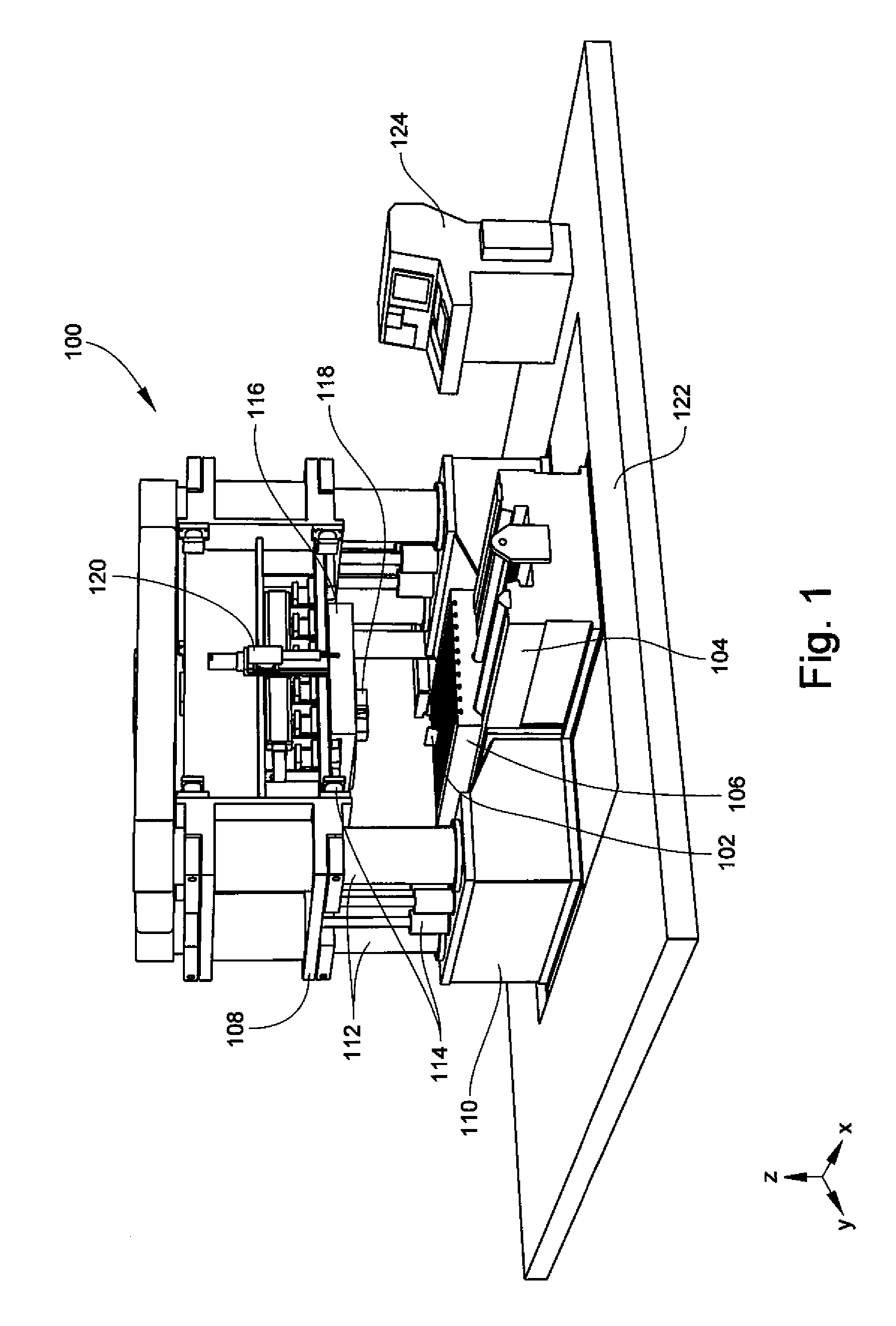
[0031]Referring to FIG. 1, an overall view of a linear friction welding machine including a dual axis forging feature according to one embodiment of the present invention is shown generally at 100. While a specific embodiment of a linear friction welding machine and some of its components are shown and described herein, it should be understood that vario...


PUM

PropertyMeasurementUnit
angleaaaaaaaaaa
oscillation frequencyaaaaaaaaaa

Abstract

A linear friction welding head apparatus for dual axis forging, the apparatus including three sets of orthogonal actuators for providing X-, Y-, and Z-planes of apparatus movement for providing Y-axis oscillation, a first forge load along a first forge axis, and a second forge load along a second forge axis. A method for dual axis forging for welding including providing a welding head for applying first and second forge loads along X- and Z-forge axes to weld at more than one interface. The forge loads may be applied at right angles to each other and have magnitudes corresponding to weld interface length.

Description

TECHNICAL FIELD AND BACKGROUND OF THE INVENTION[0001]1. Field of the Invention[0002]The present invention relates generally to the field of linear friction welding, and in particular, to apparatus and methods for dual axis forging for linear friction welding machines.[0003]2. Description of the Related Art[0004]Linear Friction Welding is a solid-state process of jointing similar or dissimilar metals that results in desirable microstructures in the weld and in the heat affected zones, producing minimal component distortion and high strength welds. In addition, linear friction welding is also a self-cleaning process, in that the oscillating motion of the process causes surface irregularities and contaminants to be expelled as flash generated during the weld, eliminating production steps.[0005]As implied by its name, linear friction welding involves heating the parts to be welded by friction generated in a controlled manner by the oscillation of the parts relative to each other. In add...

Claims


Application Information

Patent Timeline
Patent Type & Authority Patents(United States)
IPC IPC(8): B23K20/12B29C65/06
CPCB23K20/1205B23K20/10B23K20/123B23K20/125B23K20/26
Inventor ALESSI, SALVATOREPOLEN, LARRY ALEXANDERDALY, NEIL
Owner CYRIL BATH
Why Eureka
Try Eureka