Cabinet for electronic equipment

a technology for electronic equipment and cabinets, which is applied in the direction of electric apparatus casings/cabinets/drawers, lighting and heating apparatus, instruments, etc., can solve the problems of equipment error, increase in the internal temperature of the cabinet, and increase the heat load of the cabinet, so as to achieve stable and reliable operation environment

Inactive Publication Date: 2010-01-05
ORTRONICS INC
View PDF38 Cites 199 Cited by
  • Summary
  • Abstract
  • Description
  • Claims
  • Application Information

AI Technical Summary

Benefits of technology

[0012]Accordingly, a cabinet for housing and maintaining electronic equipment including a system having a gas flow distribution configuration that regulates temperature is disclosed with related methods of use, which overcome the disadvantages and drawbacks of the prior art. The system monitors and controls conditions of the cabinet including cooling of heat generating electronic components disposed therewith. The system monitors and controls conditions of the cabinet including cooling of heat generating electronic components disposed therewith. Desirably, the cabinet and related methods can accommodate increased density of equipment and high heat loads while providing cooling efficiency. The cabinet and related methods of use may be advantageously employed to provide a dynamic cooling system to accommodate additional equipment, modified equipment, and / or changing heat loads such that temperature regulation and associated cooling can be modified during use of the equipment without shutdown. It is envisioned that the cabinet is easily and efficiently manufactured and assembled.
[0013]It would be desirable if the cabinet controls airflow from a plenum floor and regulates, either manually or automatically, the amount of supply coming from a supply air system into each enclosure relative (or proportionate) to the server's power requirements and heat load. It would be most desirable if the cabinet controls the mix of room air with a colder air system delivered from the supply air system taking advantage of the room air, thus maximizing and optimizing the overall cooling capacity, simultaneously providing the room with an overall system that balances the room cooling. This provides a narrow band width of temperatures across the room resulting in a much narrower bandwidth of server intake temperatures. In order to achieve this type of control and balance, the cabinet may also provide the room and supply air mixture to the heat coming from the exhaust of all the servers. This exhaust air can be collected at the rear of the cabinet in a plenum, which is managed by a system that enables the cabinet to properly mix the elevated server exhaust air with the cooling supply and from air mixture to a desired state. The desired state can be within the specifications of a computer room air conditioner (CRAC) or a computer room air handler (CRAH) for that component or the overall system as designed per cooling of the entire data center facility.

Problems solved by technology

However, the electronic equipment stored in the cabinet typically generate heat during operation, and for example, the chassis of a blade server can create substantial amounts of heat thereby greatly increasing the heat load in the cabinet.
This heat load causes an increase in the internal temperature of the cabinet.
This temperature eventually exceeds the acceptable working temperature for the electronic equipment, resulting in overheating.
Overheating of the electronic equipment can lead to equipment error, failure, shutdown, damage, shortened life and low reliability.
This attempt, however, suffers from several disadvantages such as the requirements of cooling the entire room and its contents, the adverse effect of one cabinet temperature relative to another, and the inability to upgrade electronic equipment because the cooling capacity has reached its maximum.
These designs disadvantageously have difficulty maintaining uniform temperature within the cabinet due to greater amounts of heat being found at the top of the cabinet resulting in temperature gradients from the top to the bottom of the cabinet.
In these cases, the equipment located near the top is more prone to failure from overheating.
However, these designs do not account for temperature gradients or provide reliable temperature regulation.
Thus, these cooling designs are in effect static and unable to accommodate load changes.
In the event of equipment failure or discontinuity, many industries cannot afford down time to accommodate changes.
Further, these designs can disadvantageously waste power and cooling capacity.

Method used


Image

  • Cabinet for electronic equipment
  • Cabinet for electronic equipment
  • Cabinet for electronic equipment

Examples


Embodiment Construction

)

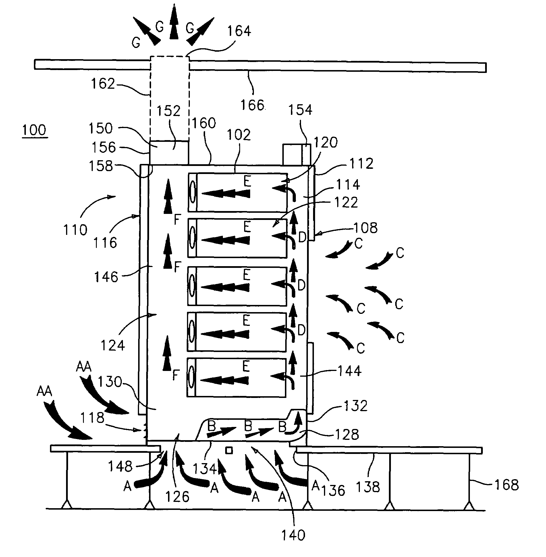
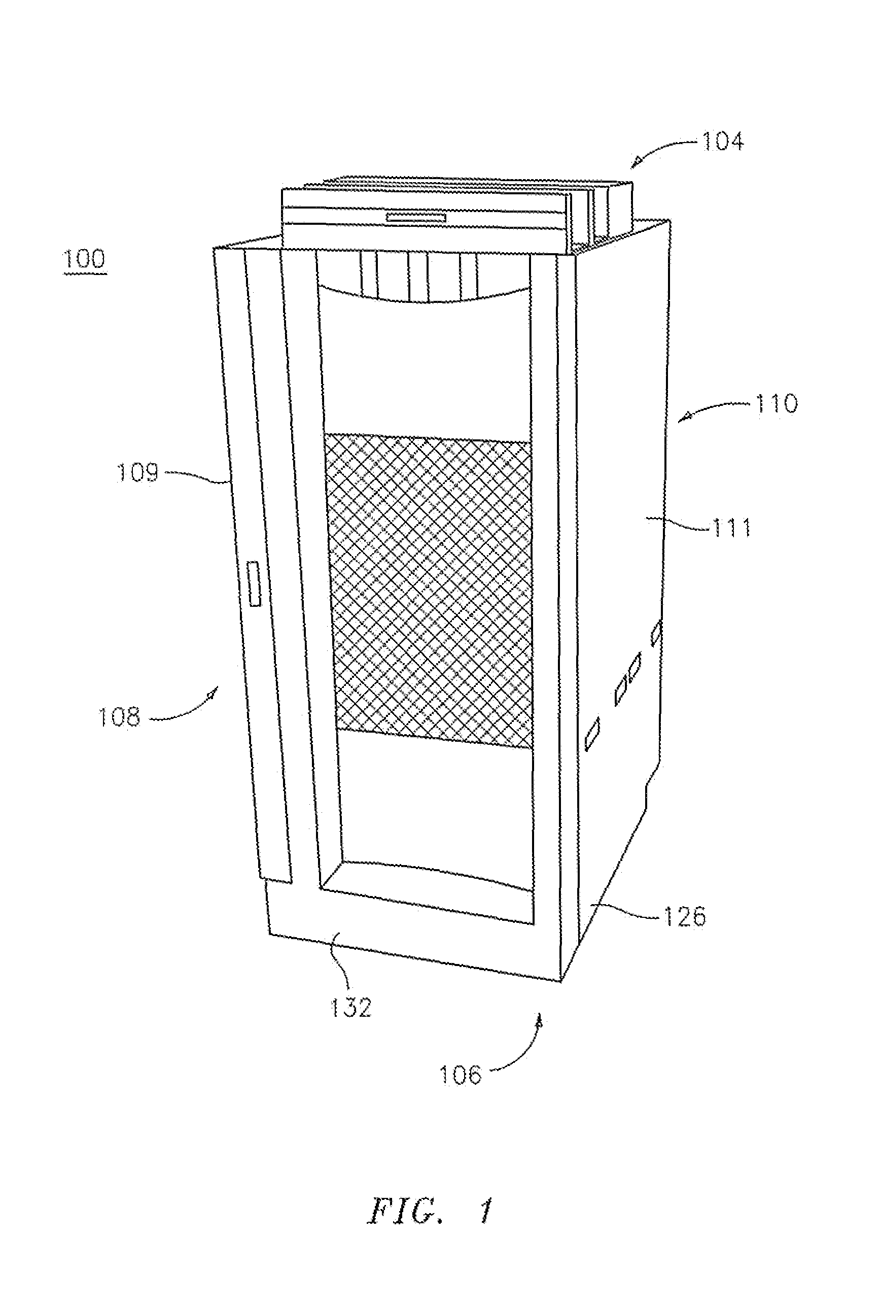
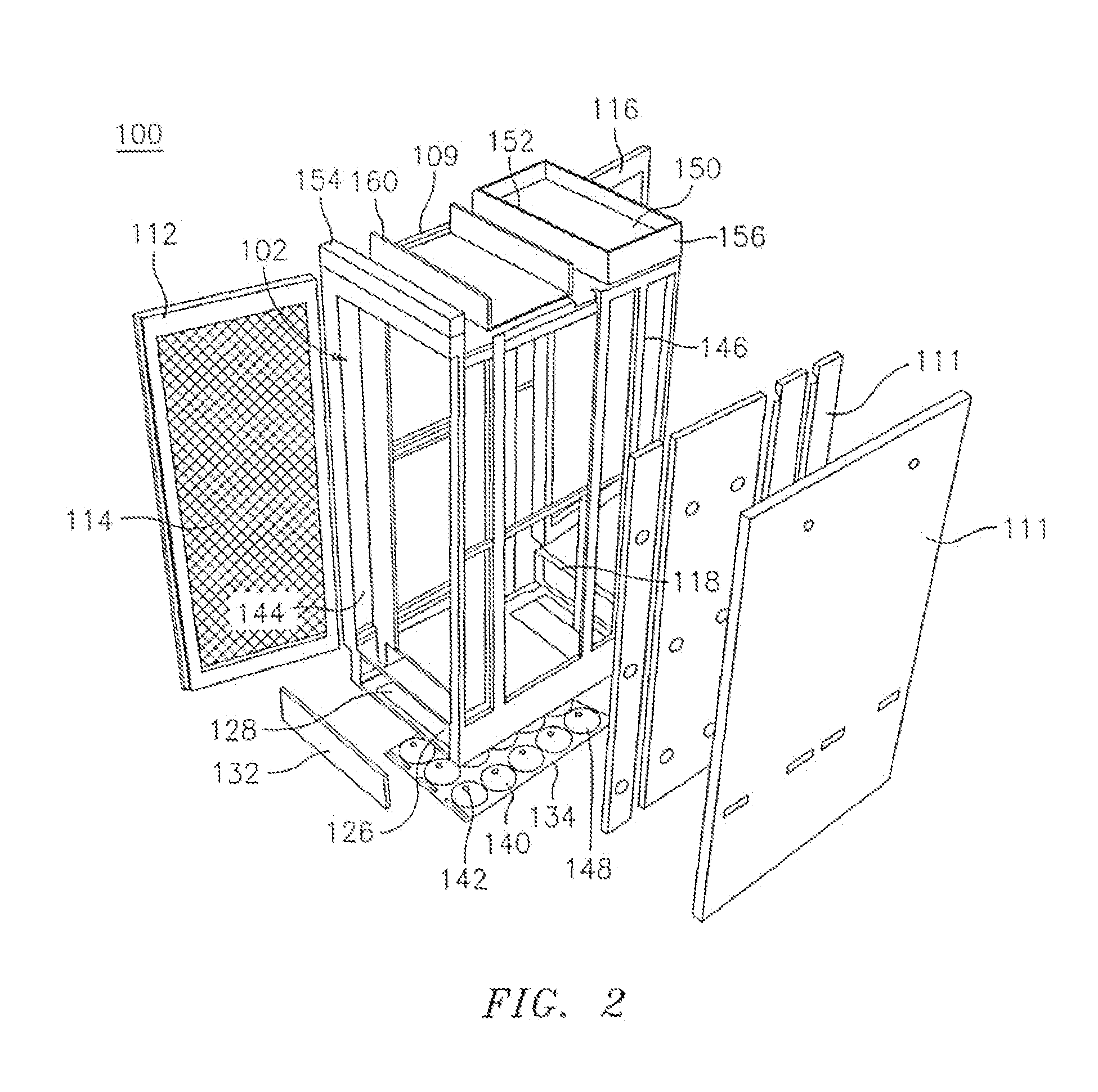
[0044]The exemplary embodiments of the cabinet system and methods of use disclosed are discussed in terms of housing and maintaining electronic equipment and more particularly, in terms of a cabinet system having a gas flow distribution configuration that regulates temperature for monitoring conditions of the system. The system includes cooling of heat generating electronic components. It is envisioned that the present disclosure may be employed with a range of applications including various types of electronic equipment. The electronic equipment may include computers, data servers, storage systems, communication systems, audio / video components, telecommunication equipment, etc. It is envisioned that the present disclosure may be employed with blade server technology. It is further envisioned that the present disclosure may be used as a dynamic cooling system to accommodate additional equipment, modified equipment, and / or changing heat loads. The temperature regulation and associat...


PUM


Abstract

An electronic equipment cabinet is provided, which includes an upper portion, a lower portion and a support configured to receive electronic equipment. The bottom portion defines a base plenum configured to receive a low temperature gas and communicates with a gas flow distribution pathway, which includes a first plenum communicating with the base plenum and configured to direct the low temperature gas to the support. The gas flow distribution pathway further includes a second plenum configured to receive a high temperature gas flow from the support and direct the high temperature gas flow to the top portion. The top portion includes at least one fan configured to direct the high temperature gas flow from the gas flow distribution pathway. A temperature sensor senses the temperature of the high temperature gas flow and communicates with a control module to control the first plenum and the at least one fan for regulating temperature.

Description

CROSS-REFERENCE TO RELATED APPLICATION[0001]The present application claims priority to U.S. Provisional Application Ser. No. 60 / 966,892 filed Aug. 30, 2007, which is herein incorporated by reference in its entirety.BACKGROUND[0002]1. Field of the Invention[0003]This invention relates generally to cabinet systems for housing and maintaining electronic equipment. More specifically, the present disclosure is directed to a cabinet system having a gas flow distribution configuration that regulates temperature for monitoring and controlling conditions of the system, including cooling of heat generating electronic components.[0004]2. Background of the Art[0005]Cabinets for storing of electronic equipment are well known. These cabinets can be designed to enclose and store electronic equipment on racks in a vertical arrangement. The electronic equipment may include computers, data servers, storage systems, communication systems, audio / video components, etc.[0006]These cabinets may also be co...

Claims


Application Information

Patent Timeline
Patent Type & Authority Patents(United States)
IPC IPC(8): H05K7/20F24F11/76
CPCF24F11/053H05K7/20745H05K7/20736G06F1/20F24F11/76
Inventor MALLIA, MICHAELFULTON, JAMES
Owner ORTRONICS INC
Why Eureka
Try Eureka