Supercharge Your Innovation With Domain-Expert AI Agents!

Digital duty cycle corrector

a digital and duty cycle technology, applied in the field of electronic devices, can solve the problem that the duty cycle of clock signals may be much higher or lower, and achieve the effect of reducing the number of clock signals

Inactive Publication Date: 2010-02-23
INT BUSINESS MASCH CORP
View PDF11 Cites 1 Cited by
  • Summary
  • Abstract
  • Description
  • Claims
  • Application Information

AI Technical Summary

Benefits of technology

The present invention provides circuits and methods for generating digital signals with desired duty cycles. One embodiment of the invention is a duty cycle correction circuit that measures the duty cycle of a signal and produces an output signal with a desired duty cycle. The circuit has a delay circuit that produces a delayed signal, which is combined with the original signal to produce the output signal with the desired duty cycle. The technical effect of this invention is the ability to generate digital signals with precise duty cycles, which can improve the accuracy and reliability of electronic devices.

Problems solved by technology

However, due to effects from distortion and skewing, a clock signal may have an undesired duty cycle much higher or lower than 50%.

Method used


Image

  • Digital duty cycle corrector
  • Digital duty cycle corrector
  • Digital duty cycle corrector

Examples


Embodiment Construction

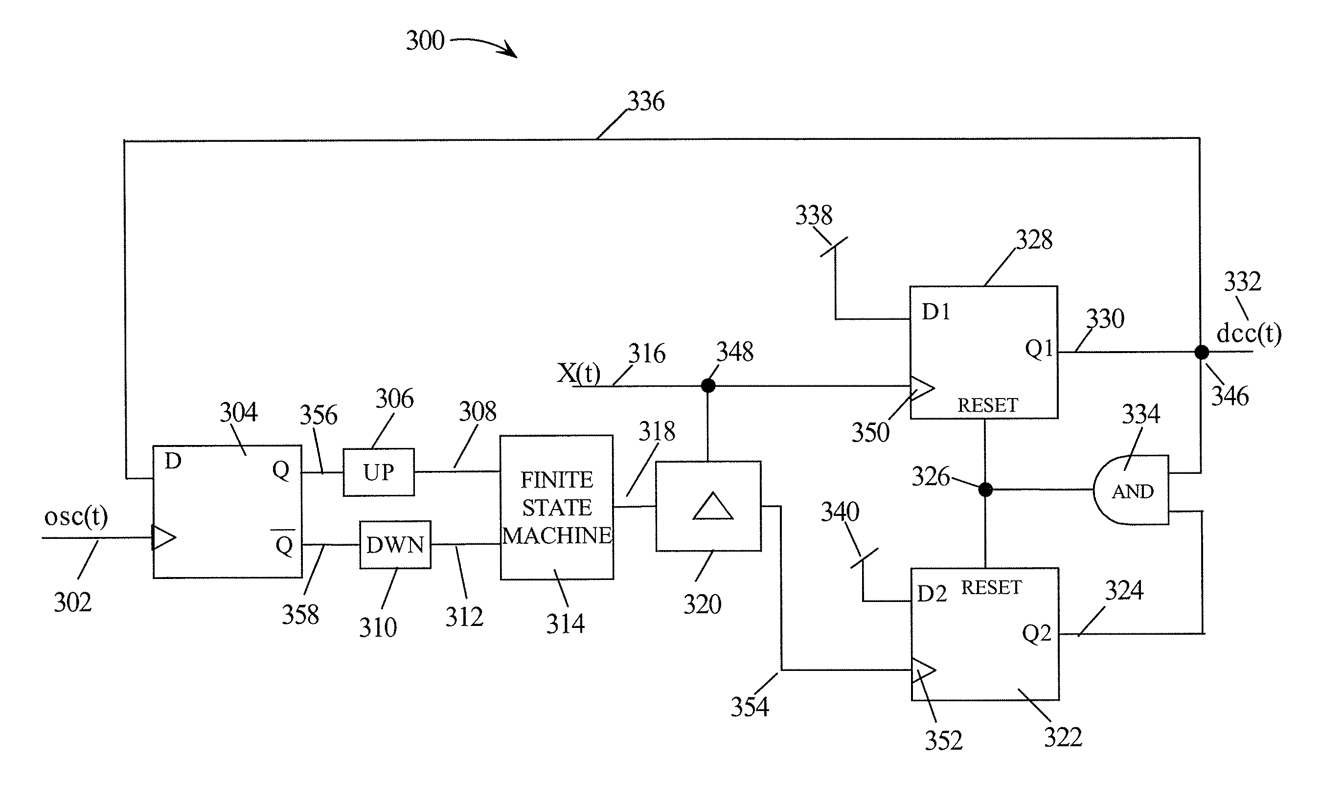
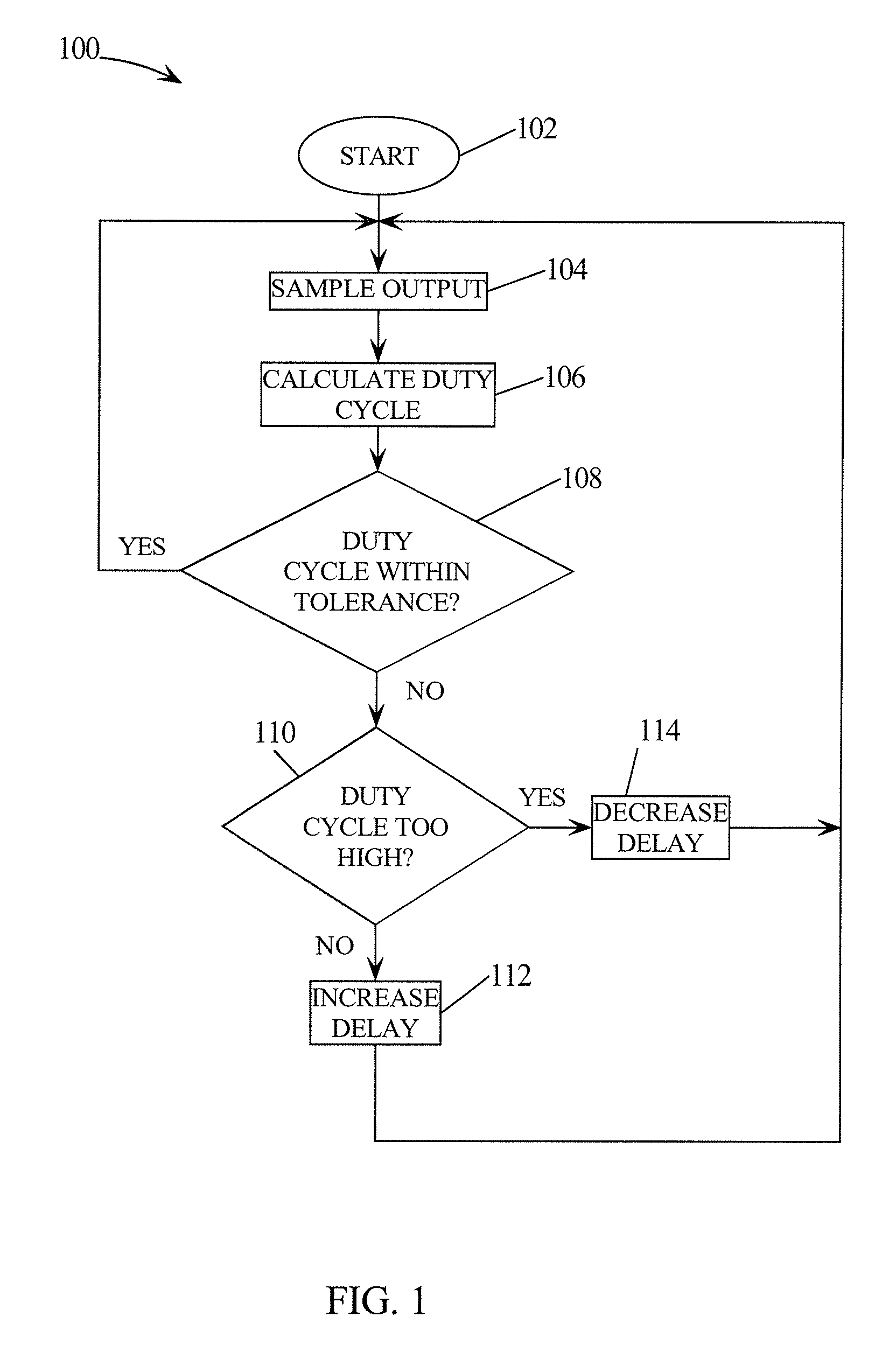
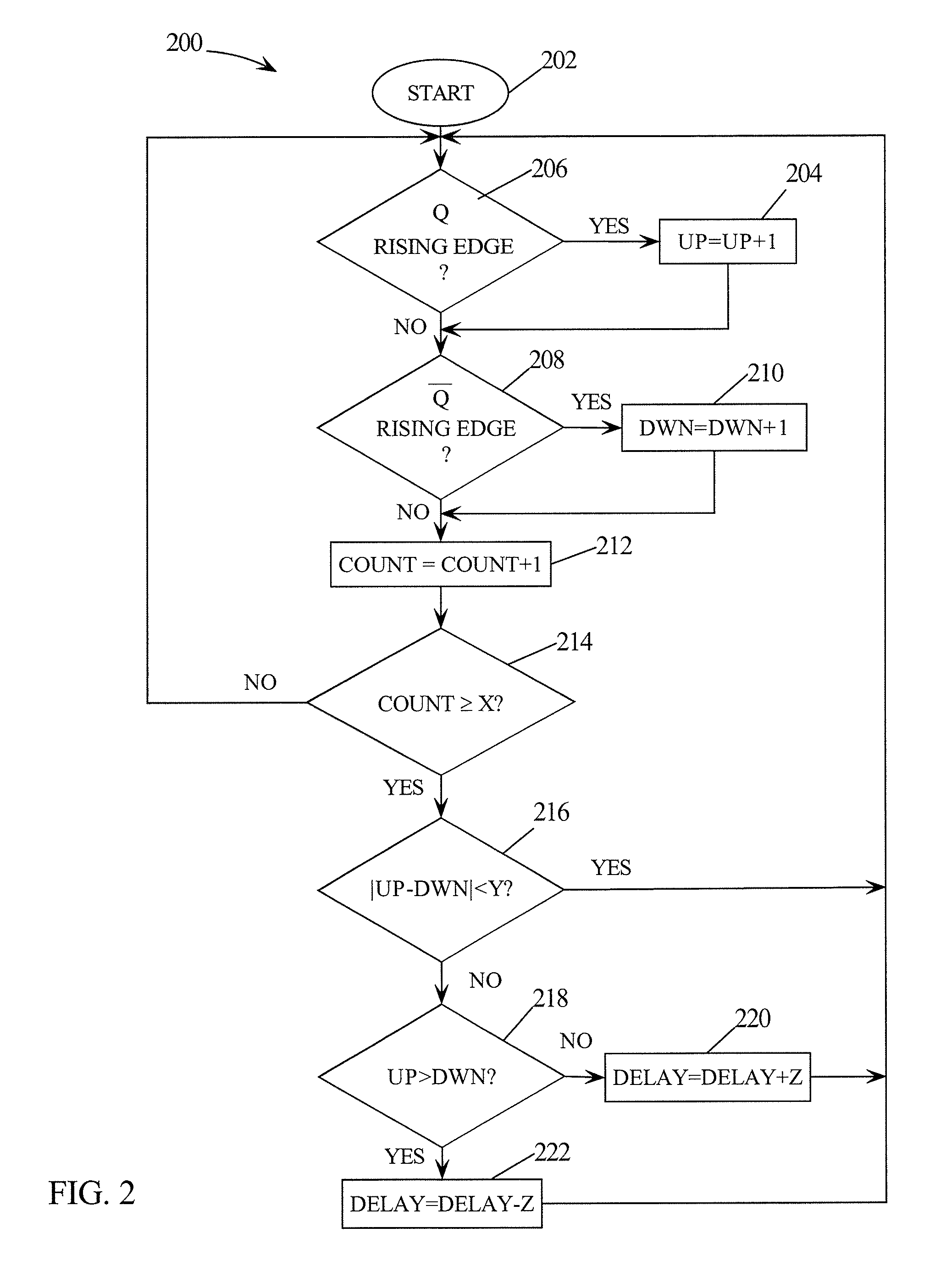
[0020]In the following description, numerous details are set forth such as specific circuit elements, gates, etc. to provide a thorough understanding of the present invention. However, it will be obvious to those skilled in the art that the present invention may be practiced without such specific details or using alternative hardware or software for accomplishing the same functions. In other instances, well-known circuits such as finite state machines have been shown in block diagram form in order not to obscure the present invention in unnecessary detail. Also, some details concerning timing considerations and the like may have been omitted inasmuch as such details are not necessary to obtain a complete understanding of the present invention and are within the skills of persons of ordinary skill in the relevant art.

[0021]Refer now to the drawings wherein depicted elements are not necessarily shown to scale and wherein like or similar elements may be designated by the same reference...


PUM


Abstract

A circuit and method of correcting the duty cycle of digital signals is disclosed. The duty cycle of an input digital signal is measured and compared to a desired duty cycle. The leading edge of the input digital signal is passed to an output. The circuit and method adjust the falling edges at the output to achieve the desired duty cycle. The falling edges occur in response to rising edges of a delayed version of the input digital signal.

Description

CROSS-REFERENCE TO RELATED APPLICATIONS[0001]The present invention is related to the following U.S. patent application which is incorporated herein by reference:[0002]Ser. No. 10 / 988,455 entitled “METHOD AND APPARATUS FOR GENERATING NON-SKEWED COMPLEMENTARY SIGNALS THROUGH INTERPOLATION” filed Nov. 12, 2004.TECHNICAL FIELD[0003]The present invention relates in general to electronics, and in particular, to adjusting the duty cycle of a signal.BACKGROUND INFORMATION[0004]Various systems and circuits require controlling the duty cycle of a clock signal. For example, some processor-based systems need a clock signal to have a duty cycle of 50%. The duty cycle of 50% may be necessary for accurate control over critical timing margins. However, due to effects from distortion and skewing, a clock signal may have an undesired duty cycle much higher or lower than 50%. Other systems employ pulse-width modulation and require generating digital signals with varying duty cycles. Therefore, it is i...

Claims


Application Information

Patent Timeline
Patent Type & Authority Patents(United States)
IPC IPC(8): H03K3/017
CPCH03K5/1565
Inventor CARPENTER, GARY D.DRAKE, ALAN J.GEBARA, FADI H.MCDOWELL, CHANDLER T.NGO, HUNG C.
Owner INT BUSINESS MASCH CORP
Features
  • R&D
  • Intellectual Property
  • Life Sciences
  • Materials
  • Tech Scout
  • Unparalleled Data Quality
  • Higher Quality Content
  • 60% Fewer Hallucinations
Learn More