Cup carrier

a carrier and cup technology, applied in the field of cups, can solve the problems of reducing stability, affecting the top of the cup is heavy, and achieve the effects of increasing the stability of the cup, increasing the contact area, and increasing the gripping for

Active Publication Date: 2010-07-27
HUHTAMAKI INC
View PDF24 Cites 37 Cited by
  • Summary
  • Abstract
  • Description
  • Claims
  • Application Information

AI Technical Summary

Benefits of technology

[0014]This socket configuration extends the stabilizing wall further into an upper region of the socket, thereby enabling the stabilizing wall to contact smaller diameter cups at a higher point. The higher contact point provides increased cup stability. Additionally, this socket configuration allows the stabilizing wall to be in contact with the cups from the uppermost contact point down to the stabilizing wall's lowermost edge, thereby providing a larger area of contact.
[0015]The socket configuration also allows the carrier to hold larger cups, such as “step-walled” cups. In one embodiment, both the upper and lower portions of the stabilizing wall are in contact with the larger cups. The fact that the shallow-angled upper portion is in contact with the larger cups is beneficial. Because the upper portion initially has a relatively shallow angle, it in turn exerts more gripping force against the cup when it is deflected outwardly by the cup's sidewall. This is especially advantageous in the case of “step-walled” cups because, as mentioned above, these types of cups only provide a small gripping area, while raising the height of the liquid load, thus making the filled cups top-heavy and more susceptible to tipping.
[0016]The carrier also includes structural features to increase strength and rigidity. For example, the carrier has a stepped center cavity or well. The center cavity comprises a stepped sidewall which resists buckling and provides increased rigidity.

Problems solved by technology

However, the design of these cups only provides a carrying tray with a smaller gripping area towards the bottom, while raising the height of the liquid load, thus making the cups top-heavy.
The problem with this approach has been that, due to the downward sloping walls, the contact point with the cup is related to the cup base size.
Therefore, cups with smaller base sizes are gripped at very low points, thereby decreasing stability.
A drawback of this approach is that it necessitates a taller structure, preventing the design from being run on certain molding machines.
Another disadvantage of this approach is that it increases the developed area of a carrier.
If the product is made to the same weight as a shorter carrier, the weight per unit area must be lower, thereby weakening the structure.
If the weight is increased to compensate, this results in higher material, energy, and transportation costs and increases the amount of natural resources used.
Another disadvantage of this approach results because bundles of these carriers create taller stacks, thereby requiring an increase in storage space and shipping costs.
However, the longer the tabs, the weaker their gripping force becomes.
Also, the rigidity of the socket structure is weakened due to the lack of material near the base of the socket.
The problem with this approach is that the practicality of the cup carrier is significantly decreased.
In addition to problems with cup fit discussed above, cup carriers also have been called upon to support heavier weights, due to the use of larger sized cups.
Some current designs have small, highly contoured areas in the center, which resist buckling, but provide little stabilization to the surrounding structure.

Method used


Image

  • Cup carrier
  • Cup carrier
  • Cup carrier

Examples


Embodiment Construction

[0025]The invention will now be described with reference to the drawing figures, in which like reference numerals refer to like parts throughout. For purposes of clarity in illustrating the characteristics of the present invention, proportional relationships of the elements have not necessarily been maintained in the drawing figures.

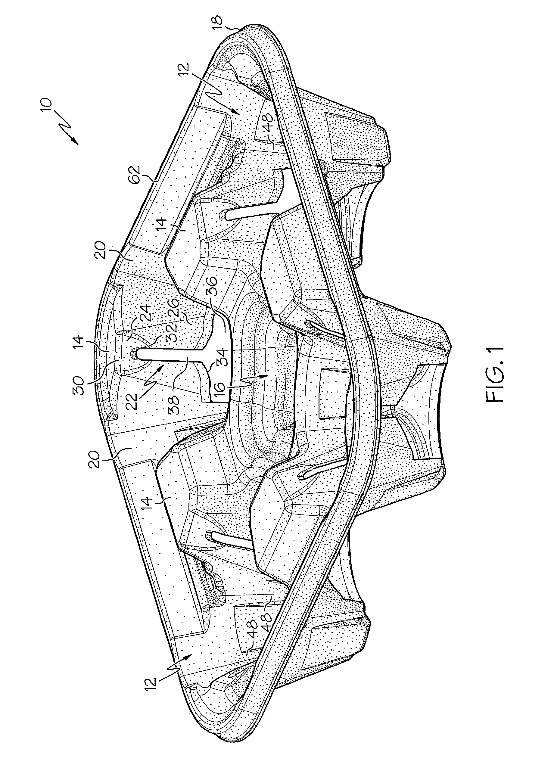
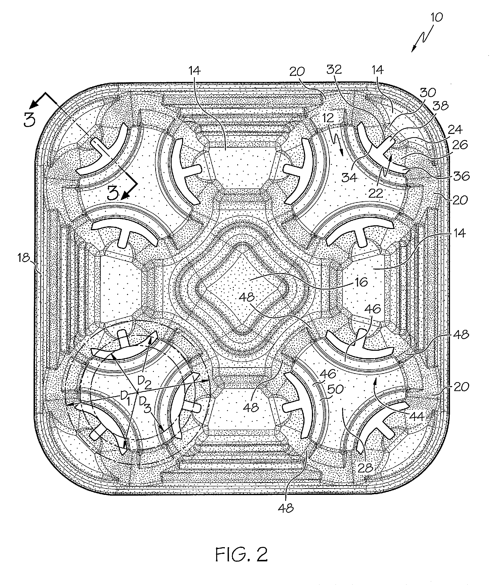
[0026]Reference numeral 10 designates generally a cup carrier 10 formed of a resilient material, such as molded fibrous pulp. The cup carrier 10 may be manufactured by molding fibrous pulp against molds or dies in a process and manner well-known in the art. In an alternative embodiment, the cup carrier 10 may be made from other materials, such as plastics, foams, or other materials having desirable strength and resiliency.

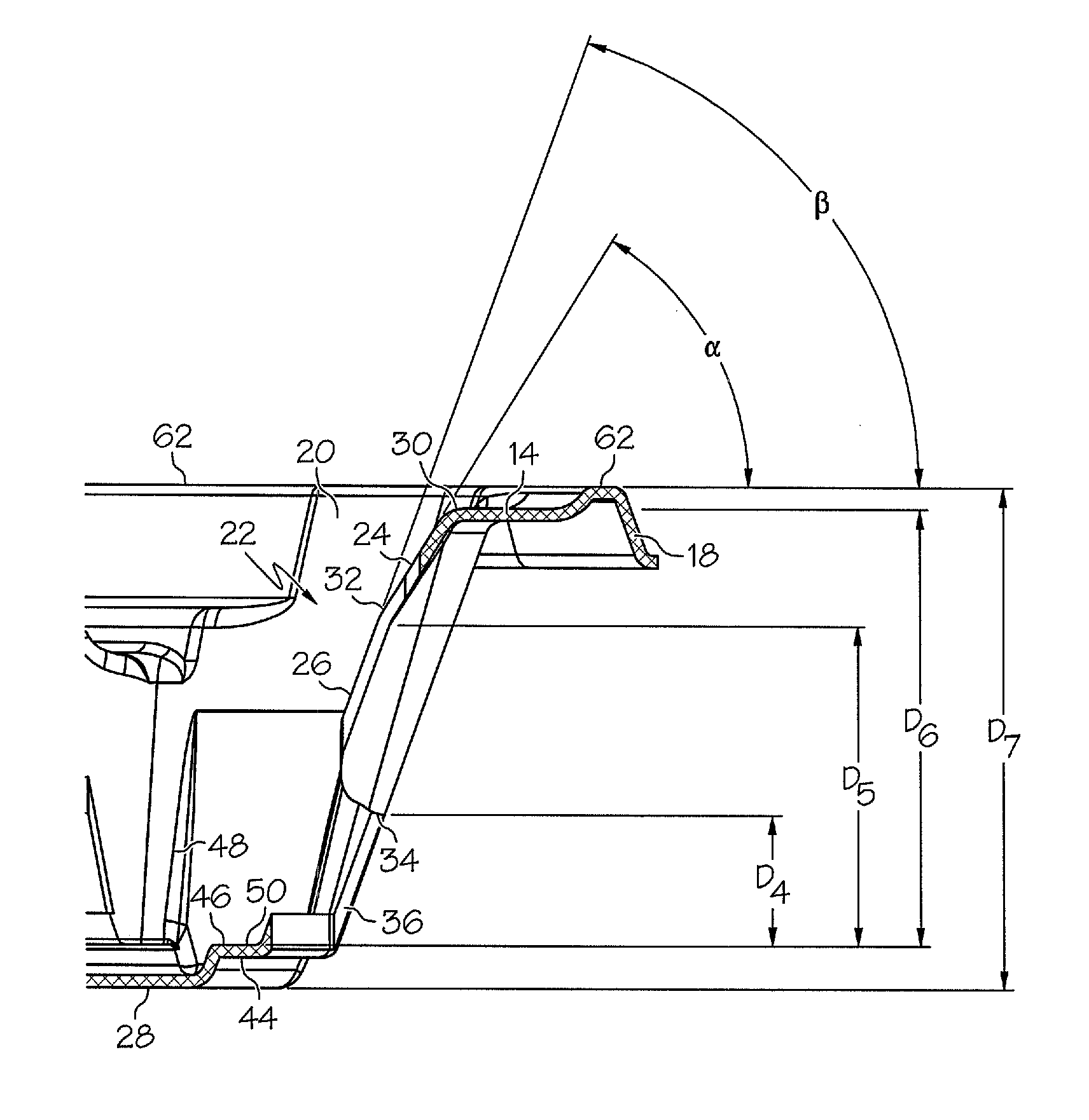
[0027]The cup carrier 10 has at least one cup-holding socket 12 molded therein to securely hold beverage cups of a variety of shapes and sizes. Such cups may be of a conventional style having a frustoconical sidewall with a circular cro...


PUM

PropertyMeasurementUnit
angleaaaaaaaaaa
angleaaaaaaaaaa
angleaaaaaaaaaa

Abstract

A cup carrier for holding beverage cups within a range of shapes and sizes is provided. The carrier has a cup-holding socket that has stabilizing shoulders and stabilizing walls extending inwardly and downwardly therefrom. The stabilizing walls include an upper portion having a relatively shallow angle and lower portions having a steeper angle. This extends the stabilizing wall further into an upper region of the socket, thereby enabling the stabilizing wall to contact smaller diameter cups at a higher point in order to increase stability. The upper portion contacts larger cups inserted into the socket. Because the upper portion initially has a relatively shallow angle, it exerts a desirable gripping force on the cups when it is deflected outwardly by the cup's sidewall. The carrier also includes a stepped center cavity for increased strength and rigidity.

Description

CROSS-REFERENCE TO RELATED APPLICATIONS[0001]None.BACKGROUND OF THE INVENTION[0002]Carrying trays for holding and carrying beverage cups are well-known and in widespread use throughout fast-food restaurants, stadiums, convenience stores, coffee shops and the like.[0003]Typically, the trays are comprised of a main body portion provided with a number of cup-holding sockets. The number of cup-holding sockets can vary, depending on the style of the carrying tray. Multiple designs exist, each having different shapes and sizes of cup-holding sockets with varying degrees of accommodation for beverage cups of different shapes and sizes.[0004]Over time the demands on these carrying trays have evolved. The fast-food restaurant industry has continued to increase maximum portion sizes, including the use of very large beverage cups for soft drinks. One type of beverage cup that has become very popular has a “step-walled” structure where the bottom portion of the cup is smaller in diameter than t...

Claims


Application Information

Patent Timeline
Patent Type & Authority Patents(United States)
IPC IPC(8): B65D1/36
CPCB65D1/36
Inventor YANG, KEEGANBRETON, DONALD V.HUSSEY, ROBERT K.
Owner HUHTAMAKI INC
Why Eureka
Try Eureka