Barrier gate with torque limiter

a technology of torque limiter and gate, which is applied in the direction of roadway safety arrangements, roads, construction, etc., can solve the problems of rotation of the spindle and damage to the gears of the transmission, and achieve the effect of avoiding costly repairs and downtim

Active Publication Date: 2010-10-26
B&B ROADWAY & SECURITY SOLUTIONS LLC
View PDF25 Cites 36 Cited by
  • Summary
  • Abstract
  • Description
  • Claims
  • Application Information

AI Technical Summary

Benefits of technology

[0007]An apparatus for controlling vehicular travel through roadway passageways including a rotationally movable barrier arm is disclosed. The present invention addresses the need to safeguard the internal linkages and gears of the motor and transmission of the barrier gate from unwanted rotation due to outside forces and thus avoiding costly repairs and downtime. The barrier gate disclosed includes a barrier arm pivotally attached to a housing. The housing is anchored to the ground and includes a motor, a transmission, a torque limiter assembly, and a rotary encoder. The motor and transmission are pivotally connected to a horizontal axis torque limiter assembly. The torque limiter assembly is connected to an auxiliary crank which is ultimately connected to the shaft that provides the rotational axis for the barrier arm. The auxiliary crank is also connected to the rotary encoder to locate the angular position of the barrier arm at any time a controller is supplied, connected to the rotary encoder to provide input signals to the motor dependent on the position of the rotary encoder. One embodiment also provides a solid vertical axis torque limiter assembly allowing movement of the barrier gate in a horizontal plane.

Problems solved by technology

But, in the event that an outside force acts on the barrier arm such as high winds or a vehicle driving under the barrier arm, the torque limiter assembly allows movement of the barrier arm in a vertical plane, but will not allow rotation of the spindle, thereby protecting the motor and transmission drive.
In other words, the friction created by the torque limiter assembly is sufficiently balanced to move the barrier when the motor and transmission drive are activated, but not sufficient to damage the gears of the transmission.

Method used


Image

  • Barrier gate with torque limiter
  • Barrier gate with torque limiter
  • Barrier gate with torque limiter

Examples


Embodiment Construction

[0020]In the descriptions that follow, like parts are marked throughout the specification and drawings with the same numerals, respectively. The drawing figures are not necessarily drawn to scale and certain figures may be shown in exaggerated or generalized form in the interest of clarity and conciseness.

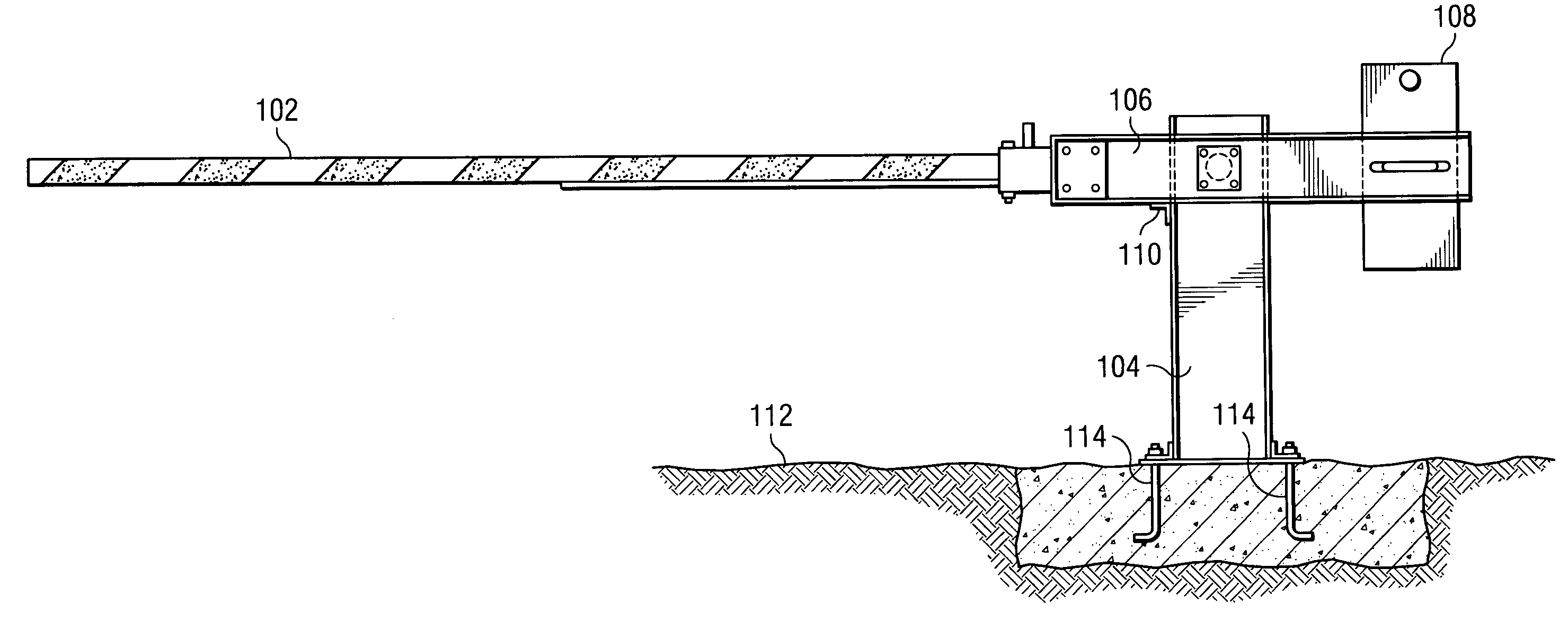
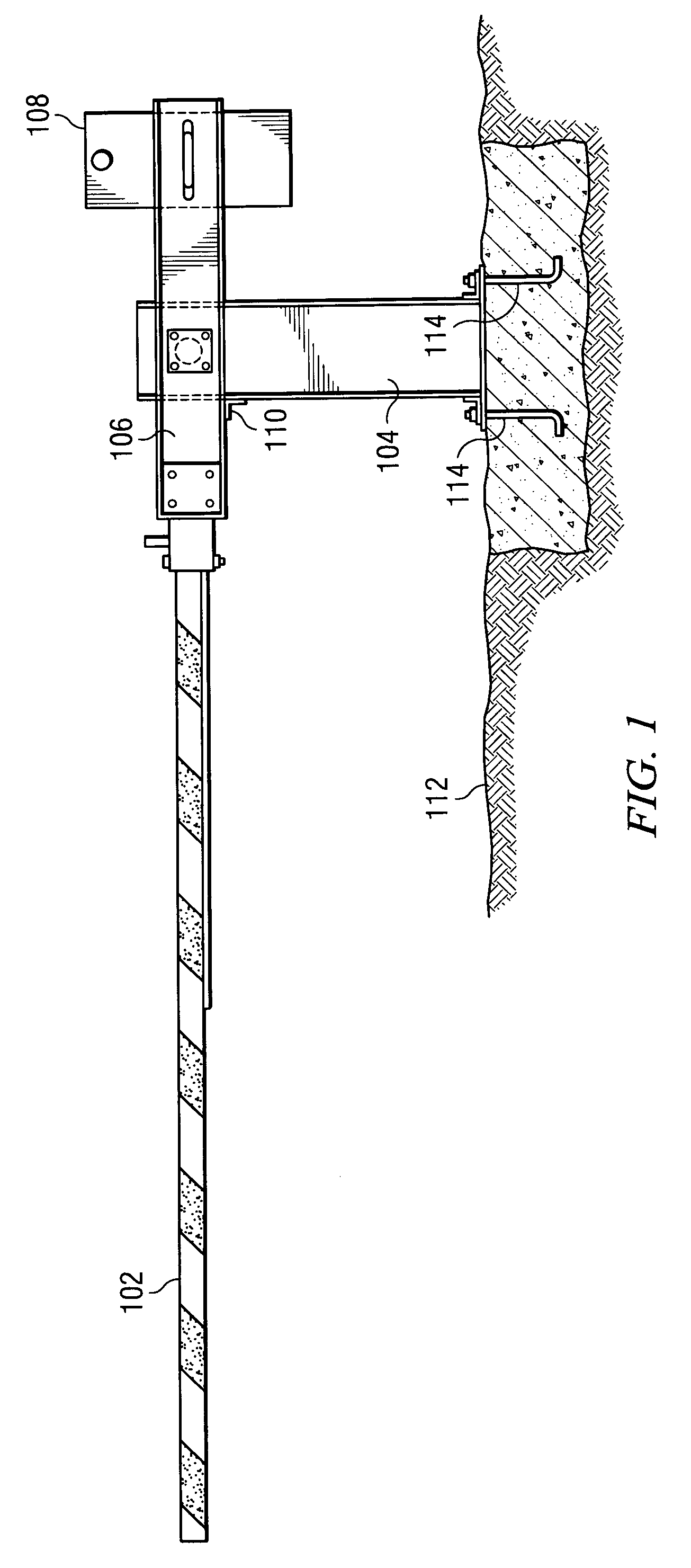
[0021]The present invention is a barrier gate for roadways that includes a rotating arm and a torque limiter. In the event the arm of the gate is moved out of position, the torque limiter prevents costly damage to the internal gears and linkages of the transmission and motor. The present invention can be installed at various vehicle passageways such as railroad crossings, high-occupancy lane entrances, draw bridges, parking lot entries and exits, etc. The specific dimensions of the present invention can be adjusted to accommodate smaller or larger applications as needed.

[0022]FIG. 1 shows a preferred embodiment of the present invention. Barrier arm 102 is connected to arm frame 106...


PUM


Abstract

Disclosed is an apparatus for a barrier gate designed to control vehicular travel through a passageway. The invention disclosed employs a barrier arm, a housing, a motor and transmission, a rotary encoder, and a torque limiter assembly. The torque limiter assembly comprises a hub, spindle, brake disk, rotor, and a gland nut. The torque limiter assembly is mounted to the motor and transmission as well as connected to the barrier arm. The torque limiter assembly provides sufficient friction to rotate the barrier arm and also protects the internal gears and linkages of the transmission and motor from costly repair / replacement by preventing any unwanted rotation. In the event an outside force rotates the barrier arm, the rotary encoder in cooperation with a controller instantly recognizes the position of the barrier arm and further acts as a limit switch to send a signal to the motor to stop when the barrier arm is in place.

Description

FIELD OF THE INVENTION[0001]This invention relates to barrier gates for roadways. In particular, this invention relates to an apparatus and method for preventing damage to the internal gears that move the barrier gate through the use of a torque limiter connected between the control arm of the gate and the transmission of the motor.BACKGROUND OF THE INVENTION[0002]Barrier gates that incorporate the use of a pivoting barrier arm are in widespread use. Typical uses of such devices include high occupancy freeway lane entrances, controlled parking lot entries and exits, toll booth lanes, airport entries and exits, railroad crossings, and drawbridges. Most often designs include some sort of actuator to initiate movement of the barrier arm such as a remote control, weight sensitive sensor, or an electronic card reader. Once a signal is received, a motor drives the internal mechanisms to rotate the barrier arm into the open or closed position. The motor and the transmission that convert th...

Claims


Application Information

Patent Timeline
Patent Type & Authority Patents(United States)
IPC IPC(8): E01F13/00
CPCE01F13/06
Inventor CAUSEY, LYNN R.CAUSEY, ROGER D.
Owner B&B ROADWAY & SECURITY SOLUTIONS LLC
Why Eureka
Try Eureka