Screen and projection system

a projection system and projection screen technology, applied in the field of projection screen and projection system, can solve the problems of non-uniform light intensity distribution on the screen, difficulty in achieving sufficiently bright display, and loss of approximate half of the light projected by the projection screen, and achieve the effect of effective representation

Inactive Publication Date: 2011-04-26
SEIKO EPSON CORP
View PDF19 Cites 10 Cited by
  • Summary
  • Abstract
  • Description
  • Claims
  • Application Information

AI Technical Summary

Benefits of technology

[0008]The first plane is the surface of the screen that faces the viewer, and the second plane is the surface of the screen that is opposite to the viewer. By transmitting the light focused through the optical element on the second plane side from the transmissive portion toward the first plane, the light incident on the second plane can efficiently be outputted toward the first plane. The size of the transmissive portion can thus be small on the first plane side, so that the reflective portion can be large in size. A large reflective portion allows efficient reflection of the light incident on the first plane. Moreover, by employing a configuration in which the light incident on the second plane is refracted through the optical element, the light intensity distribution of the light incident on the second plane is made uniform. By thus reflecting and transmitting the light, a screen for displaying a bright image with a uniform light intensity distribution is provided.
[0021]It is preferable that the absorbing portion is formed on the first plane side of the optical element. The entire light incident on the second plane thus enters the optical element. This configuration reduces the loss of the light incident on the second plane, part of which otherwise directly enters the absorbing portion.

Problems solved by technology

Therefore, approximately half the light that the projectors have projected is lost, so that sufficiently bright display is difficult to achieve.
Further, since the light reflected off the diffuser layer and the light transmitted through the diffuser layer mostly diverge in the direction away from the projectors, likely resulting in a non-uniform light intensity distribution on the screen in which areas closer to the periphery of the screen are darker.
In the technology described in JP-A-2006-227581, since the light from one projector is divided into two directions, sufficiently bright display is difficult to achieve, likely resulting in a non-uniform light intensity distribution as in JP-A-9-114003.
Further, since the display on one side of the screen is reversed right and left from the display on the other side of the screen, the technology is not suitable for applications involving display of characters and the like, and hence only suitable for limited applications.
As described above, both the technologies of related art encounter difficulty obtaining a bright image with a uniform light intensity distribution by reflecting and transmitting light.

Method used


Image

  • Screen and projection system
  • Screen and projection system
  • Screen and projection system

Examples


Embodiment Construction

[0040]Embodiments of the invention will be described below in detail with reference to the drawings.

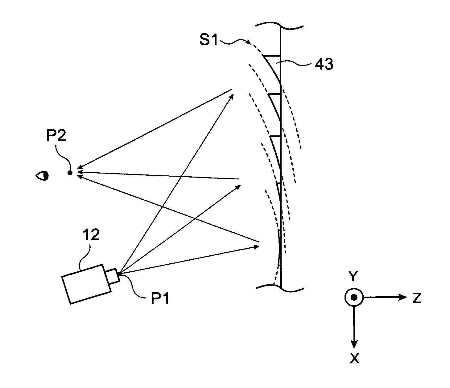
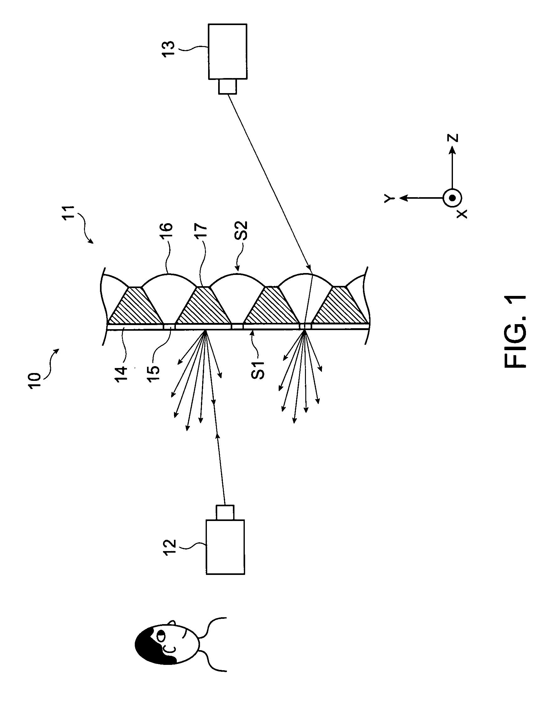
[0041]FIG. 1 shows a schematic configuration of the projection system 10 according to an embodiment of the invention. The projection system 10 includes a screen 11, a first projector 12, and a second projector 13. In FIG. 1, the screen 11 is shown in the form of the cross-sectional configuration of the key portion. The first projector 12 projects light representing an image signal onto a first plane S1 of the screen 11. The second projector 13 projects light representing an image signal onto a second plane S2 of the screen 11. The first plane S1 is the plane of the screen 11 that faces the viewer. The second plane S2 is the plane of the screen 11 that is opposite to the first plane S1. The screen 11 is disposed along the X direction and the Y direction substantially perpendicular to the X direction. The Z direction is substantially perpendicular to the X and Y directions.
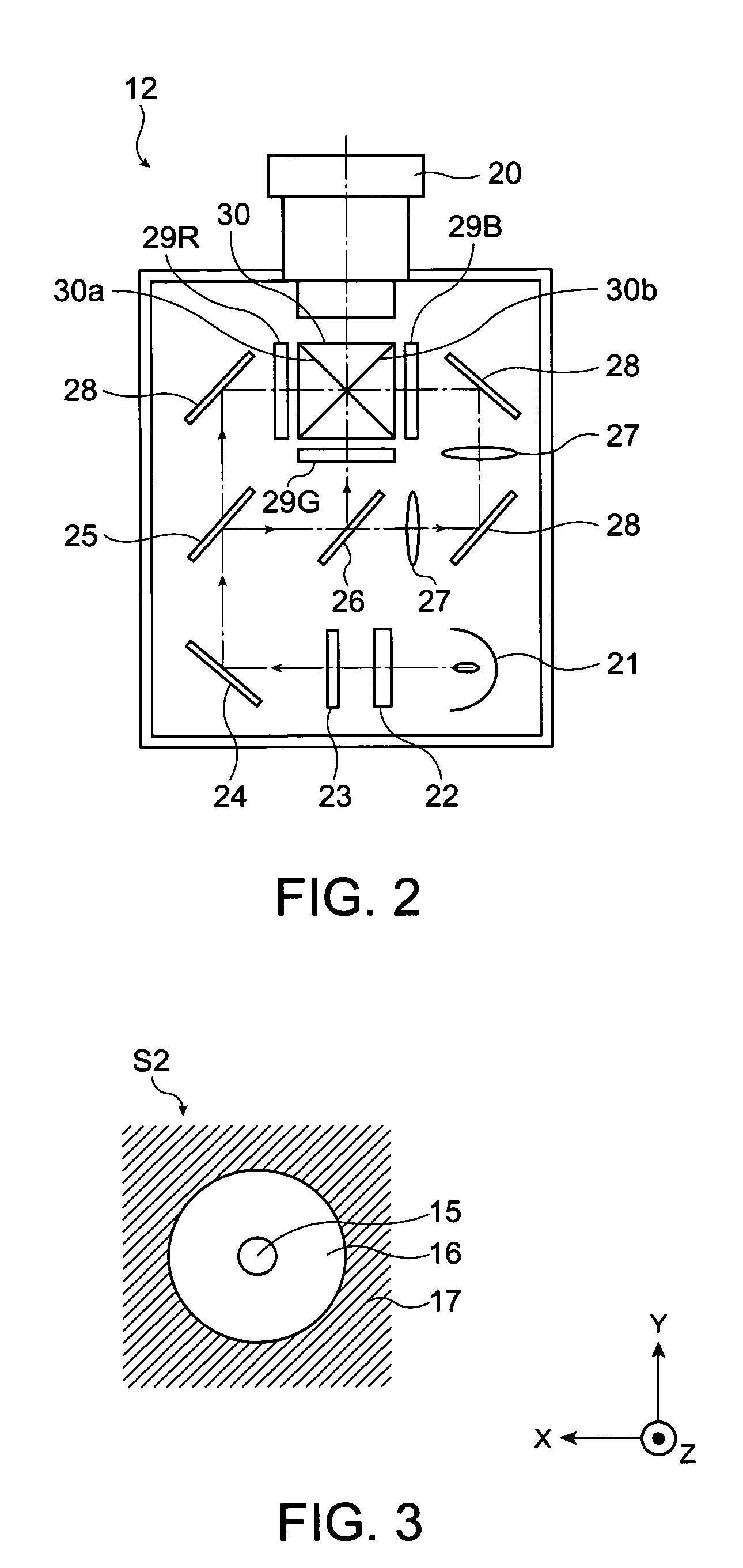
[0042]FIG. 2 ...


PUM


Abstract

A screen including a first plane and a second plane opposite to the first plane, at least one of which is illuminated with light, includes a reflective portion that reflects the light incident on the first plane, a transmissive portion that transmits the light incident on the second plane toward the first plane, and an optical element that focuses the light incident on the second plane such that the focused light is incident on the transmissive portion.

Description

BACKGROUND[0001]1. Technical Field[0002]The present invention relates to a screen and a projection system, and particularly to a technology of a screen used with a projector that projects light representing an image signal.[0003]2. Related Art[0004]A projector projects light representing an image signal and uses the light reflected off a screen or the like to display an observable image on the same side as the projector with respect to the screen. On the other hand, when the light representing an image signal passes through a screen or the like, an observable image can be displayed on the side opposite to the projector with respect to the screen. When a screen that can reflect and transmit light is used, a projector disposed on the viewer's side with respect to the screen and a projector disposed on the side opposite to the viewer with respect to the screen can be used for effective display. For example, JP-A-9-114003 and JP-A-2006-227581 propose technologies of screen that reflects...

Claims


Application Information

Patent Timeline
Patent Type & Authority Patents(United States)
IPC IPC(8): G03B21/26G03B21/28G03B21/20G02B3/08G03B21/00G03B21/60G03B21/602G03B21/62
CPCG03B21/26
Inventor SHINOZAKI, JUNICHIRONAGATE, TAKASHITANIGUCHI, SEIICHI
Owner SEIKO EPSON CORP
Why Eureka
Try Eureka