Connector with a connecting member with a screw portion penetrating the insulators and terminals of two mating terminal housings

a technology of connecting member and screw portion, which is applied in the direction of contact member penetrating/cutting insulation/cable strand, coupling device connection, propulsion by batteries/cells, etc., can solve the problems of obstructed downsizing of the connector, and achieve the effect of reducing the stroke distance of the connecting member

Inactive Publication Date: 2011-06-14
HITACHI CABLE
View PDF15 Cites 21 Cited by
  • Summary
  • Abstract
  • Description
  • Claims
  • Application Information

AI Technical Summary

Benefits of technology

[0027]According to one embodiment of the invention, a connector is constructed such that it includes a first screw part and a second screw part having a larger screw pitch than the first screw part and, when the first screw part is screwed into a threaded screw hole of a first terminal housing, a pressing force can be provided from two directions so as to sandwich each contact between a head (i.e., an elastic member for pressing the head) of a connecting member and a second insulation member. Therefore, even when the stroke distance is shorter than before, a pressing force sufficient to fix the contacts can be obtained. Thus, the stroke distance of the connecting member can be shortened and the dimension in the overlapping direction (i.e., in the stacking direction) can be thereby reduced, so that the connector can be further downsized.

Problems solved by technology

However, the technique of JP-B-4037199 may have the following problem.
Since a pace of fastening the bolt is synchronized with a pace of pressing the contacts (the contacts being pressed with strength corresponding to the fastening distance of the bolt), a predetermined fastening distance is needed to get a predetermined pressing force and thus may be an obstacle to the downsizing of the connector.

Method used


Image

  • Connector with a connecting member with a screw portion penetrating the insulators and terminals of two mating terminal housings
  • Connector with a connecting member with a screw portion penetrating the insulators and terminals of two mating terminal housings
  • Connector with a connecting member with a screw portion penetrating the insulators and terminals of two mating terminal housings

Examples


Embodiment Construction

[0042]The preferred embodiments according to the invention will be explained below referring to the drawings.

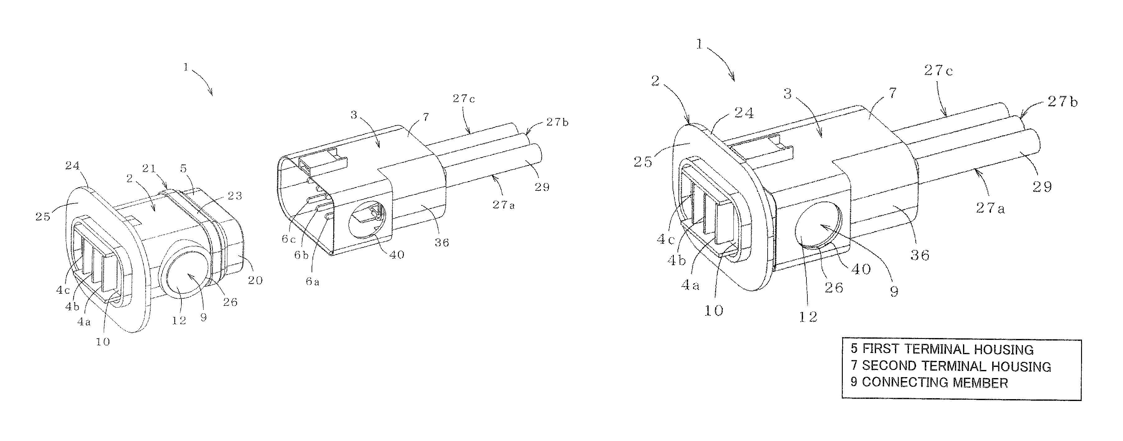
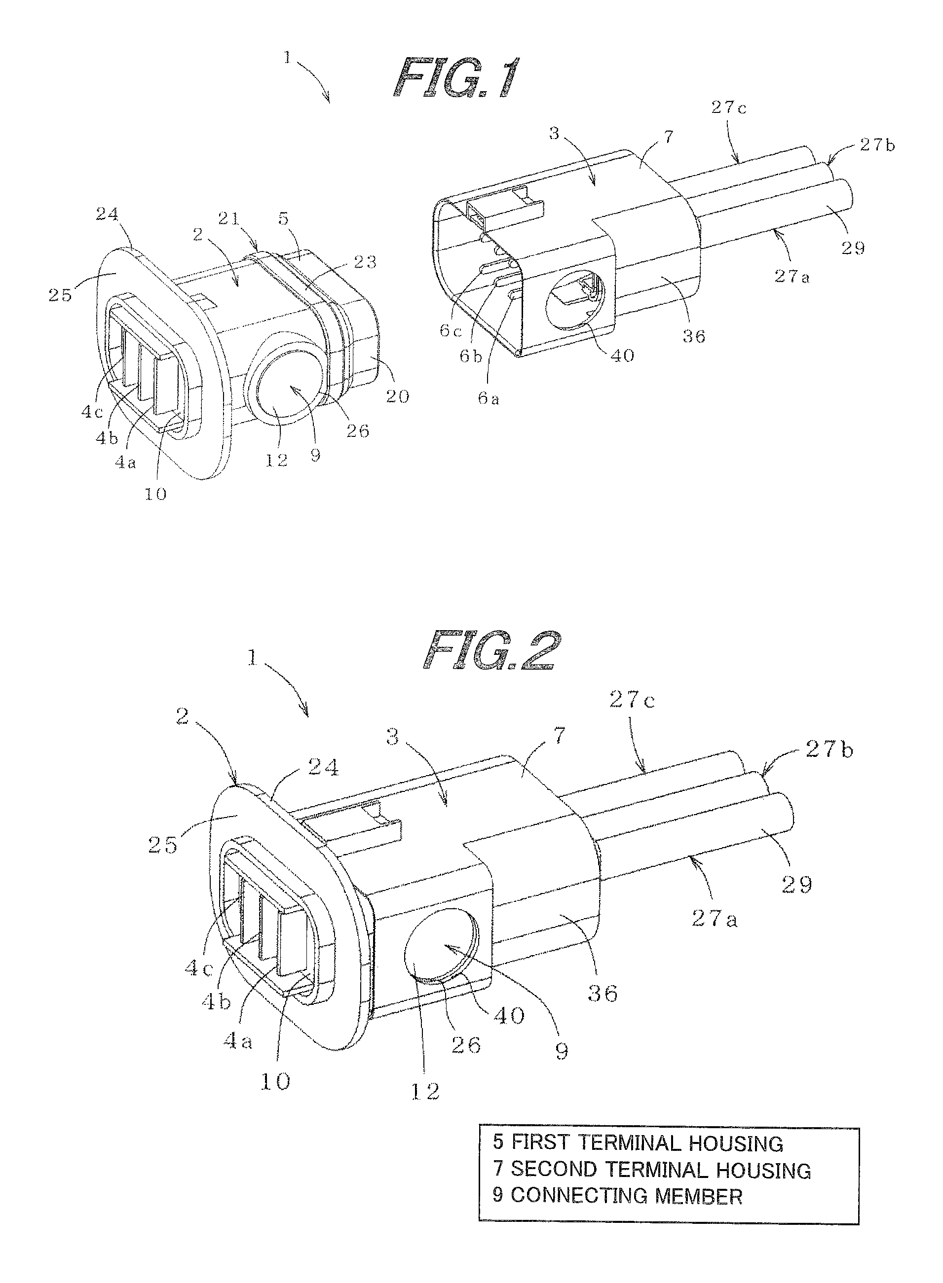
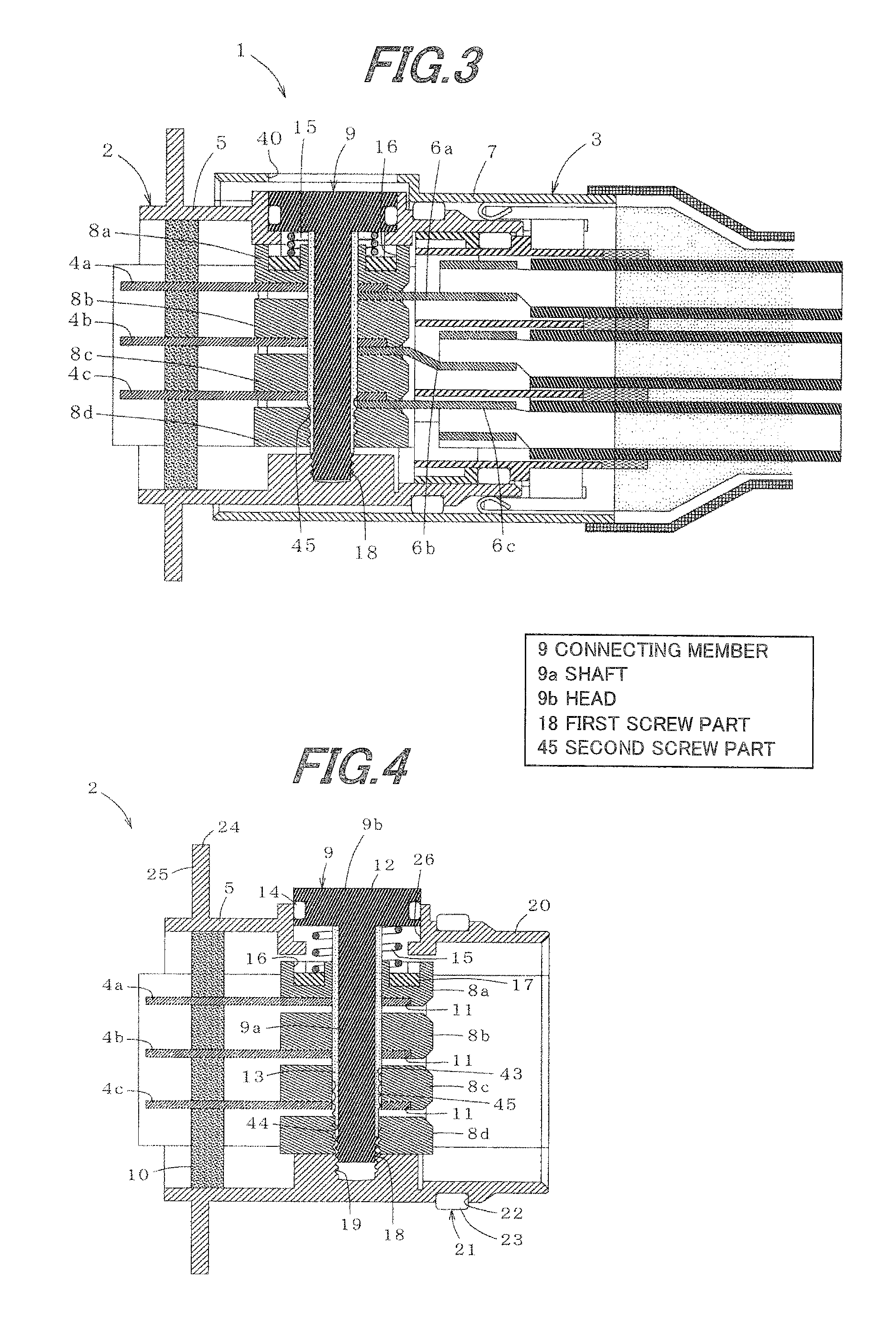
[0043]FIG. 1 is a perspective view schematically showing a first connector part and a second connector part that constitute an connector according to one embodiment of the invention, FIG. 2 is a perspective view schematically showing the connector after the first connector part and the second connector part are fitted to each other, and FIG. 3 is a cross-sectional view schematically showing the connector after the first connector part and the second connector part are fitted to each other.

[0044]As shown in FIGS. 1 to 3, a connector 1 according to the embodiment includes a first connector part 2 and a second connector part 3 and is used for collectively connecting a plurality of power-supply lines by allowing the connector parts 2, 3 to be fitted to each other.

[0045]More particularly, the connector 1 includes the first connector part 2 having a first terminal housing 5 in whic...


PUM


Abstract

A connector includes a first terminal housing with a plurality of first connecting terminals aligned and accommodated therein, a second terminal housing with a plurality of second connecting terminals aligned and accommodated therein, a plurality of insulation members aligned and accommodated in the first terminal housing, a connecting member including a head and a shaft connected to the head. The shaft and/or the head includes a first screw part to screw the connecting member into the first terminal housing and/or the second terminal housing. The shaft includes a second screw part to screw into an insulation member of the plurality of the insulation members at a forward end in an insertion direction of the connecting member. The second screw part includes a screw pitch greater than the first screw part.

Description

[0001]The present application is based on Japanese patent application No. 2009-287889 field on Dec. 18, 2009, the entire contents of which are incorporated herein by reference.BACKGROUND OF THE INVENTION[0002]1. Field of the Invention[0003]This invention relates to a connection structure, for use in eco-friendly cars, such as hybrid vehicles, electric vehicles and the like, and in particular, for being capable of use for a portion to connect a power harness, which is used for large power transmission.[0004]2. Description of the Related Art[0005]In hybrid vehicles, electric vehicles and the like which have remarkably developed in recent years, a power harness, which is used for large power transmission for connection between devices, has at its one end a connector, which consists of two separate portions: a male connector portion with a male terminal and a first terminal housing accommodating that male terminal, and a female connector portion with a female terminal connected with the...

Claims


Application Information

Patent Timeline
Patent Type & Authority Patents(United States)
IPC IPC(8): H01R24/00
CPCB60L11/1803H01R13/639B60L2240/36H01R9/03Y02T10/7005H01R2105/00H01R2201/26H01R13/621B60L50/51Y02T10/70
Inventor UMETSU, JUNTAKEHARA, HIDEAKIFUKUDA, KUNIHIROSUZUKI, SACHIOKATAOKA, YUTA
Owner HITACHI CABLE
Why Eureka
Try Eureka