Door handle for refrigerator

a door handle and refrigerator technology, applied in the field of refrigerators, can solve the problems of inconvenience for users, inability to meet users' desires, and changes are separated, so as to achieve the effect of improving durability, reducing inconvenience, and relatively strengthening the door handl

Inactive Publication Date: 2012-02-07
LG ELECTRONICS INC
View PDF25 Cites 55 Cited by
  • Summary
  • Abstract
  • Description
  • Claims
  • Application Information

AI Technical Summary

Benefits of technology

[0047]With the door handle for a refrigerator according to the present invention constructed as above, the strength of the door handle is relatively reinforced. Thus, there are advantages in that no deformation occurs upon operation of the door handle, durability thereof is improved, and various decorations can be made thereon.
[0048]Further, according to an embodiment of the present invention, components of the door handle are firmly coupled to one another. Thus, there are advantages in that the strength of the entire door handle is relatively improved and it is possible to minimize the occurrence of relative deformation between components with different properties.
[0049]Moreover, according to another embodiment of the present invention, there is an advantage in that it is possible to make various kinds of door handles with minimized design changes of their components.
[0050]In addition, according to the present invention, since a luminous body is contained in the door handle and emits light, there are advantages in that a user can easily identify the door handle even in the dark and the door handle itself can act as a light, resulting in better convenience to the user.

Problems solved by technology

First, each of the handle bars 6 of the conventional door handles 5′ and 7′ is an elongated single bar. Thus, when a user grips and pulls the handle bars 6 with his / her hand, the handle bars 6 are repeatedly deformed and restored due to their elastic deformation. Thus, during use, coupling between the handle bars 6 and the handle holders 6′ and 8′ may be loosed so that the handle bars 6 come off or are shaken, which may cause a problem of inconvenience to the user.
Therefore, the main bodies 6a and 8a raise the handle holders 6′ and 8′, thereby causing a problem in that the decorations 6b and 8b relatively insensitive to thermal changes are separated or shaken.
In addition, since the handle bars 6 and 8 in the prior art are constructed such that the decorations 6b and 8b are simply mounted on the main bodies 6a and 8a, there is a problem in that it is not possible to meet desires of users who want a variety of designs.

Method used


Image

  • Door handle for refrigerator
  • Door handle for refrigerator
  • Door handle for refrigerator

Examples


Embodiment Construction

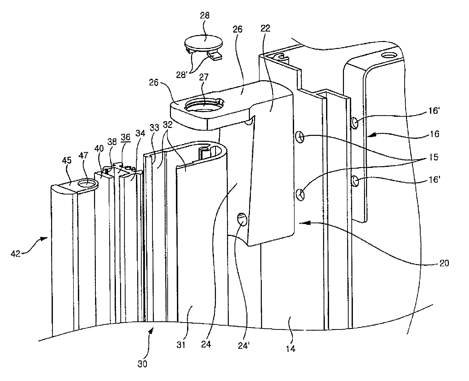
[0087]Meanwhile, FIG. 5 shows a door handle according to another embodiment of the present invention. For description of this embodiment, components corresponding to those of the previous embodiment described above are designated by like reference numerals but added by 100, and only different components will be described below.

[0088]In this embodiment, a coupling rib 131′ is formed to be elongated in a handle bar body 131 of a handle bar 130 in a longitudinal direction of the handle bar body 131. The coupling rib 131′ is used for coupling with cover end coupling pieces 145. The coupling rib 131′ is formed over the entire length of the handle bar body 131. This is because the handle bar body 131 is formed by extruding a metallic material.

[0089]Hooking ribs 132 are formed in parallel at both longitudinal ends of an open portion of the handle bar body 131. Hooking protrusions 133 are formed at front ends of the hooking ribs 132 over the entire lengths of the hooking ribs 132. The hooki...


PUM


Abstract

A decoration is installed in a seating channel provided in a handle bar. The seating channel with the decoration installed therein is shielded by a transparent or translucent handle cover. Cover end coupling pieces are provided at both ends of the handle cover and coupled with coupling ribs of a handle bar body of the handle bar or a cover base. The cover end coupling pieces protrude and extend from both ends of the handle cover to be perpendicular to other portions. A luminous body or jewel may be used as the decoration.

Description

TECHNICAL FIELD[0001]The present invention relates to a refrigerator, and more particularly, to a door handle for a refrigerator, which is used for opening or closing a door that opens or closes a storage space in the refrigerator.BACKGROUND ART[0002]The configuration of a refrigerator mounted with a conventional door handle will be described with reference to FIG. 1. A storage space 3 is formed inside a refrigerator main body 1. The storage space 3 may be partitioned into a refrigerating chamber and a freezing chamber, which are located at upper and lower portions of the main body 1, respectively. A pair of refrigerating chamber doors 5 for selectively opening or closing the refrigerating chamber are provided at both ends of a front face of the upper portion of the main body 1, and a freezing chamber door 7 for selectively opening or closing the freezing chamber is installed at a front face of the lower portion of the main body 1.[0003]Door handles 5′ and 7′ are installed on the re...

Claims


Application Information

Patent Timeline
Patent Type & Authority Patents(United States)
IPC IPC(8): A47B95/02
CPCA47B95/02E05B1/0015F25D23/028Y10T16/458F25D2400/18Y10T16/459F25D2400/06
Inventor BAE, SUNG-WOOKAN, JONG-HYEOKCHO, HYEON-POCHOI, CHANG-BONG
Owner LG ELECTRONICS INC
Why Eureka
Try Eureka