Supercharge Your Innovation With Domain-Expert AI Agents!

Electronically heated tool for use in installation of anchoring devices employing hot melt adhesives

a technology of hot melt adhesives and electric heating, applied in the direction of ohmic-resistance heating, ohmic-resistance heating details, fastener tools, etc., can solve the problems of affecting the adhesion of the anchoring device, the tool does not provide functionality, and the drop off is easy to occur before. , to achieve the effect of convenient installation and removal

Inactive Publication Date: 2012-07-17
HSU CHIA WEN
View PDF35 Cites 0 Cited by
  • Summary
  • Abstract
  • Description
  • Claims
  • Application Information

AI Technical Summary

Benefits of technology

The solution prevents finger burns, ensures secure engagement and removal, avoids overheating by notifying the user of heating completion, and simplifies the process by enabling direct removal of anchoring devices without additional tools.

Problems solved by technology

1) When the user manipulates to sleeve the anchoring device 3 on the heating head 2, his or her fingers have to be relatively close to the heating head 2, which is prone to cause a burning accident.
2) Since the anchoring device 3 is engaged to the heating head 2 by only sleeving the protruding forwardly protruding nose 301 on the same, it is prone to drop off before it is pressed against the support surface 4.
3) The electrically heated tool does not provide functionality for notifying the user that the hot melt adhesive 304 has been heated for a sufficient time period. As a result, the hot melt adhesive 304 may be overheated, thereby affecting adversely adhesion of the anchoring device 3 onto the support surface 4.
4) When the user employs the electrically heated tool to reheat the hot melt adhesive 304 for removing the anchoring device 3, another tool (not shown) has to be incorporated in use to enable removal of the anchoring device 3 from the support surface 4. It is inconvenient for use in this viewpoint.

Method used


Image

  • Electronically heated tool for use in installation of anchoring devices employing hot melt adhesives
  • Electronically heated tool for use in installation of anchoring devices employing hot melt adhesives
  • Electronically heated tool for use in installation of anchoring devices employing hot melt adhesives

Examples


Embodiment Construction

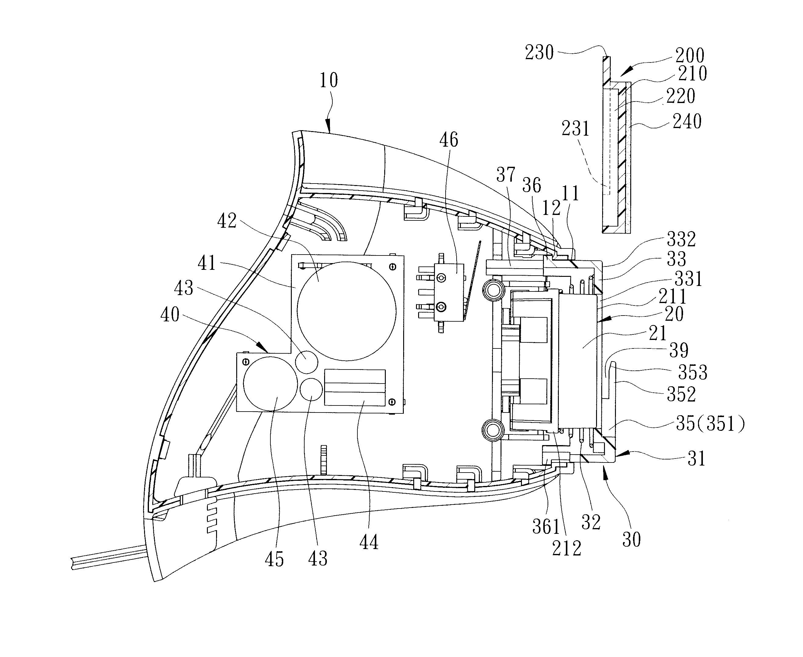
[0021]Referring to FIGS. 3, 4 and 5, the preferred embodiment of an electrically heated tool according to the present invention is adapted for use in installation of an anchoring device 200. The anchoring device 200 has a forwardly protruding nose 210 for carrying hot melt adhesive 240, a rear recess 220, and a rim 230 surrounding the rear recess 220. The rim 230 has a pair of bottom end portions 231. The electrically heated tool comprises: a housing 10, a heating unit 20, a movable unit 30 and an alarming unit 40.

[0022]The housing 10 has an opening 11 and a position-limiting shoulder 12 surrounding the opening 11.

[0023]The heating unit 20 is disposed in the housing 10, and has a heating head 21 that extends forwardly out of the housing 10 through the opening 11, and that has a front pressing surface 211, and an annular shoulder 212 disposed behind the front pressing surface 211.

[0024]The movable unit 30 includes a movable member 31 disposed movably on the heating head 21 and extend...


PUM


Abstract

An electrically heated tool adapted for an anchoring device includes a housing having an opening, a heating head extending forwardly out of the opening, and a movable member disposed movably on the heating head and extending forwardly out of the opening. The movable member has an engagement hole permitting extension of the heating head therethrough, a front annular surface, a loading portion disposed on the front annular surface, and a loading space defined between the loading portion and the front annular surface. The movable member is movable relative to the heating head between an extended position whereat a front pressing surface of the heating head is spaced apart from a forwardly protruding nose of the device, and a retracted position whereat the front pressing surface contacts the nose. A spring is disposed for biasing the movable member toward the extended position.

Description

BACKGROUND OF THE INVENTION[0001]1. Field of the Invention[0002]This invention relates to an electrically heated tool, and more particularly to an electrically heated tool for use in installation of anchoring devices employing hot melt adhesive.[0003]2. Description of the Related Art[0004]As shown in FIGS. 1 and 2, a conventional electrically heated tool (as disclosed in the U.S. Pat. No. 4,771,161) includes a housing 1 and a heating head 2. The housing 1 has a planar front wall 101 provided with a front recess 102 dimensioned to receive an anchoring device 3. The heating head 2 extends forwardly into the front recess 102. The anchoring device 3 has a forwardly protruding nose 301 carrying a hot melt adhesive 304, and a rear recess 302 surrounded by a circular rim 303. When a user intends to adhere the anchoring device 3 to a support surface 4, the anchoring device 3 has to be first placed into the front recess 102 so as to sleeve the forwardly protruding nose 301 on the heating hea...

Claims


Application Information

Patent Timeline
Patent Type & Authority Patents(United States)
IPC IPC(8): B25B31/00
CPCB25B31/00B25B33/00
Inventor HSU, CHIA-WEN
Owner HSU CHIA WEN
Features
  • R&D
  • Intellectual Property
  • Life Sciences
  • Materials
  • Tech Scout
  • Unparalleled Data Quality
  • Higher Quality Content
  • 60% Fewer Hallucinations
Learn More