Power transmission mechanism

a transmission mechanism and power technology, applied in the direction of rotary clutches, fluid couplings, gearings, etc., to achieve the effect of reducing hydrodynamic influences

Active Publication Date: 2012-09-25
SCHAEFFLER TECH AG & CO KG
View PDF15 Cites 1 Cited by
  • Summary
  • Abstract
  • Description
  • Claims
  • Application Information

AI Technical Summary

Benefits of technology

[0006]The object of the invention is to refine a power transmission mechanism of the type named above so that a further improvement is achieved in the connecting behavior of a lockup clutch specifically in a configuration having an actuating mechanism that may be subjected to any desired pressure, as well as a reduction of the hydrodynamic influences on the lockup clutch, which can result in self-closure of the latter, using especially simple means.
[0008]The solution according to the invention makes it possible to effectively shield the piston element from axial forces resulting from the hydrodynamic effects, in particular by shifting the support of the axial force resulting from the hydrodynamic effects from the piston element to a different element with simple means, free of additional modification efforts for the additional sub-assemblies.
[0009]The influencing element can be designed in various ways. The decisive factor is that this moving fluid which is present in the intermediate space provided between influencing element and piston element produces a dragging effect that reduces the rotational speed of the moving fluid to the rotational speed of the piston.
[0010]According to a one embodiment, the influencing element may be designed as a disk-shaped or ring-shaped element which, for example, has a surface that is completely closed in the circumferential direction. Such additional elements can be integrated into the power transmission mechanism in a manner that saves construction space especially well.
[0011]According to another embodiment, the influencing element can be designed as a formed element, for example, as a conically shaped element, when viewed in cross section. The element is present in general as a formed sheet metal part, in particular a deep drawn part, from the disk-shaped semifinished material. The formed element has a connecting zone in the area of the inner circumference, which is used to make a rotationally fixed connection with a connecting element and which has an inclined contour in the axial direction when viewed in cross section, i.e., with a constant or non-constant change in diameter, forming an annular sleeve. In this manner the stiffness of the component is increased and the risk of abrasion reduced.

Problems solved by technology

In general, however, for 3-channel versions of the power transmission mechanism when used in vehicles the problem exists of being able to ensure clean and jerk-free regulation of the lockup clutch, due to the hydrodynamic influences of moving fluids.

Method used


Image

  • Power transmission mechanism
  • Power transmission mechanism
  • Power transmission mechanism

Examples


Embodiment Construction

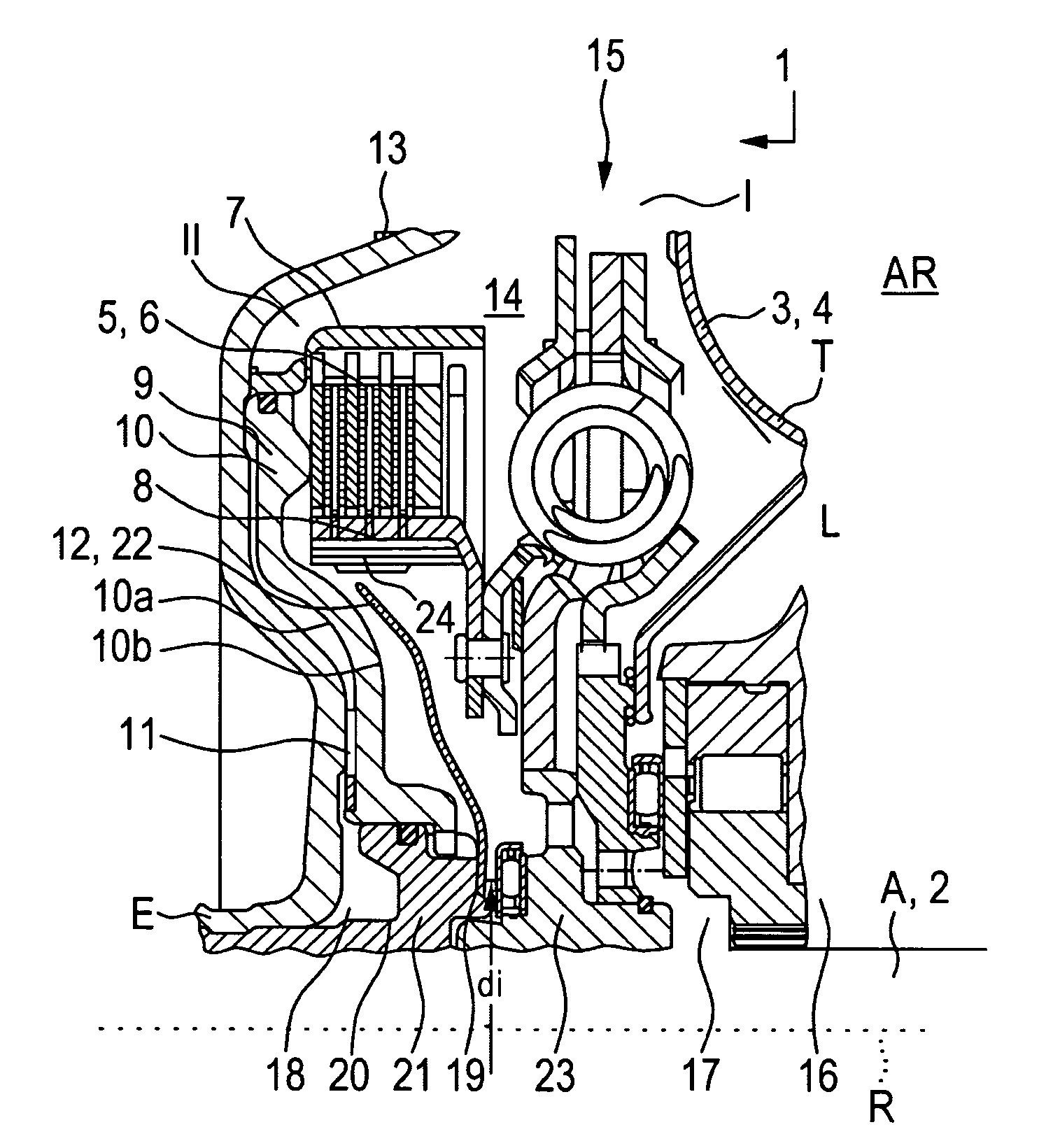
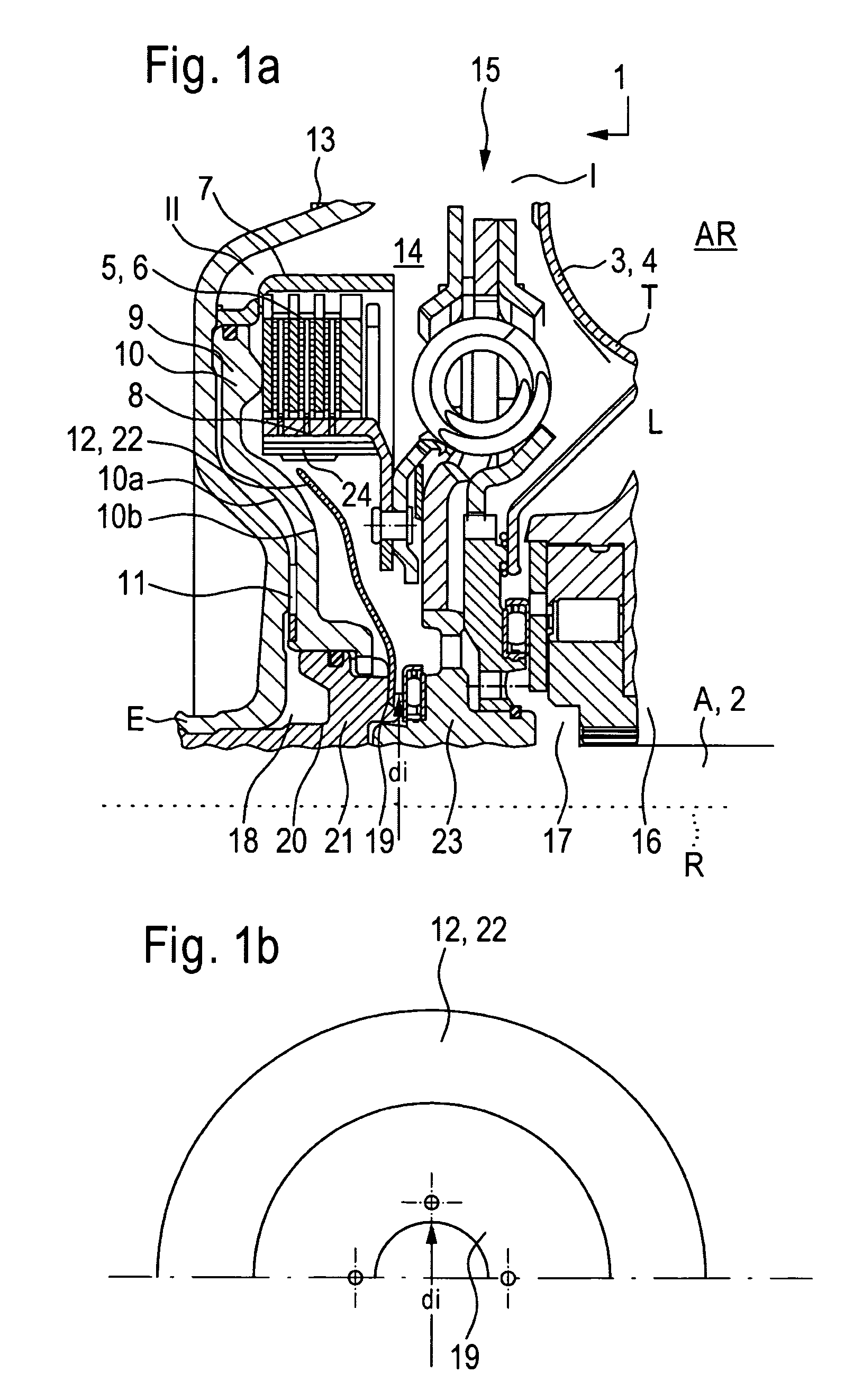
[0024]FIG. 1a illustrates, in a schematically simplified depiction in an axial sectional view, a power transmission mechanism 1 designed according to the invention for use in power trains, in particular in power trains of vehicles, between a driving engine and an output drive. The output drive is normally formed by a transmission, not depicted here. Power transmission mechanism 1 assumes the function of power transmission, as well as of a speed variator / torque converter within certain bounds. To that end, power transmission mechanism 1 has at least one input E and one output A. Input E is couplable at least indirectly with a driving engine, not shown here, while output A can be connected to a take-off, normally the gear unit downline from the power transmission mechanism 1. Situated between input E and output A is a hydrodynamic component 3. The latter includes at least one primary wheel (not shown) which functions as a pump wheel when power is transmitted between input E and output...


PUM


Abstract

A power transmission mechanism for transmitting power between a driving engine and an output drive, including: an input and an output; a hydrodynamic component with a pump wheel and a turbine wheel; an apparatus for at least partially bridging over the hydrodynamic component, the apparatus including a control device with a piston element that is chargeable with pressurizing agent; an influencing element for influencing a difference in speeds of rotation of moving fluids on both sides of the piston element, the influencing element rotatable in rotational synchronicity with the piston element, which extends outward in the radial direction free of any direct connection with the piston element, and which is situated in the radial direction at least in the range of the outside diameter, forming at least part of an axial space with the piston element.

Description

CROSS-REFERENCE TO RELATED APPLICATIONS[0001]This application claims priority from German Patent Application No. 10 2007 059 405.6, filed on Dec. 10, 2007, which application is incorporated herein by reference.FIELD OF THE INVENTION[0002]The invention relates to a power transmission mechanism, in particular for transmitting power between a driving engine and an output drive, including a hydrodynamic component and an apparatus for at least partially bridging over the hydrodynamic components.BACKGROUND OF THE INVENTION[0003]A power transmission component including a hydrodynamic speed variator / torque converter and a lockup clutch is previously known for example from published patent DE 44 33 256 A1. The power transmission mechanism includes an input that is connected to a driving engine with a rotationally fixed connection. This is formed for example by a housing with a wall that runs at least approximately radially. The lockup clutch situated between the latter and the turbine wheel ...

Claims


Application Information

Patent Timeline
Patent Type & Authority Patents(United States)
IPC IPC(8): F16H3/72
CPCF16H45/02F16H2045/021F16H2045/0294F16H2045/0284F16H2045/0247
Inventor DANIEL, BENJAMINKRAUSE, THORSTEN
Owner SCHAEFFLER TECH AG & CO KG
Why Eureka
Try Eureka