
Power transmission device

a technology of power transmission device and clutch, which is applied in the direction of rotary clutch, fluid coupling, gearing, etc., to achieve the effect of simple means, improved actuation behavior of lock-up clutch, and reduced hydrodynamic influen

Inactive Publication Date: 2013-02-26
SCHAEFFLER TECH AG & CO KG
View PDF11 Cites 1 Cited by
  • Summary
  • Abstract
  • Description
  • Claims
  • Application Information

AI Technical Summary

Benefits of technology

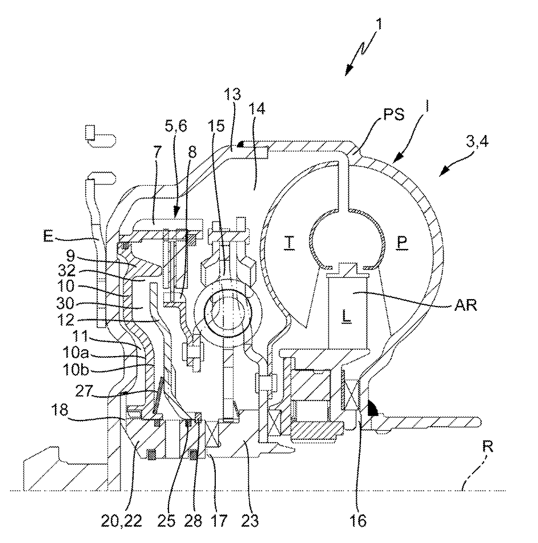
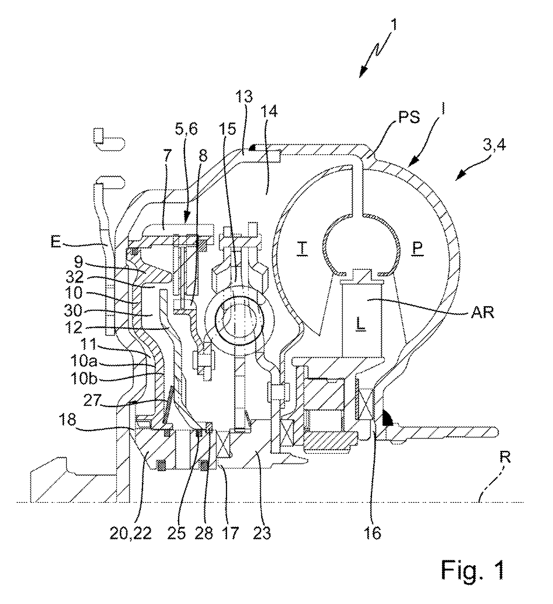
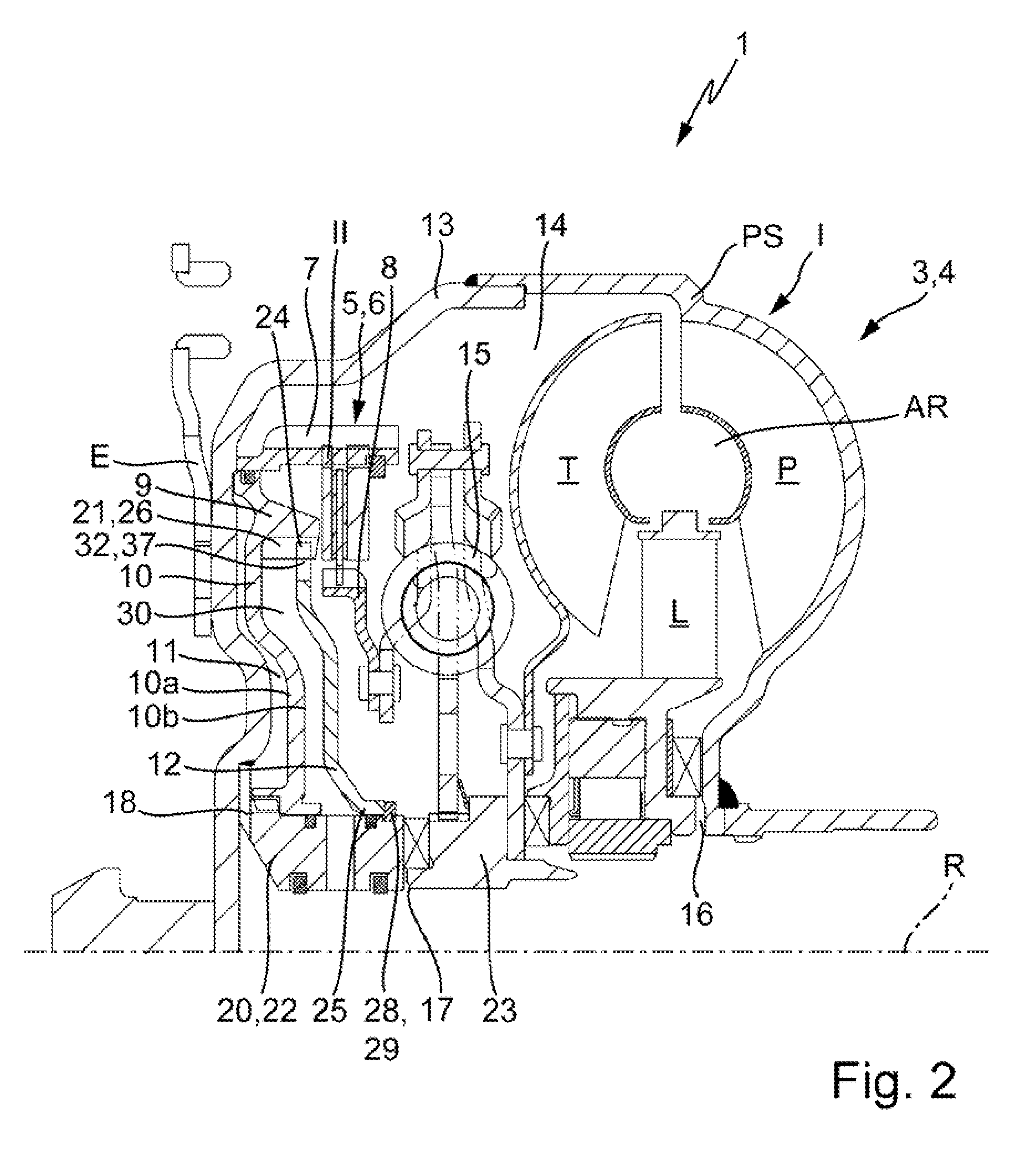
[0007]The invention is based on the task to further develop a power transmission device of the kind mentioned above, in which a further improvement of the actuation behavior of a lock-up clutch can be attained with particularly simple means, especially in a configuration with an actuation device that can be exposed to arbitrary pressure, as well as a reduction of the hydrodynamic influences on the lock-up clutch that can lead to automatic closure of the latter.
[0009]The solution according to the invention enables effective shielding, of the piston element of the servo unit of the shiftable clutch device, from axial forces resulting from hydrodynamic effects, in particular through extension of the support of axial forces from the piston element of the servo unit resulting from the hydrodynamic effects on another element in the form of a further piston element with simple means, free from additional modification demand for individual subassemblies.
[0010]The other piston element can be executed in different ways. What is decisive is the flow medium provided in the space between the latter and the piston element of the servo unit, which causes a dragging effect, thus the circulation rate of the flow medium in this range is reduced during the deceleration mode or increased during the drag mode by up to the rotation speed of the piston element of the servo unit of the shiftable clutch device.

Problems solved by technology

Generally, however, the problem exists in the application in vehicles, with regard to the ability to implement clean and jerk-free adjustment of the lock-up clutch, due to the hydrodynamic influences of flow media.

Method used


Image

  • Power transmission device
  • Power transmission device
  • Power transmission device

Examples


Embodiment Construction

[0027]At the outset, it should be appreciated that like drawing numbers on different drawing views identify identical, or functionally similar, structural elements of the invention. While the present invention is described with respect to what is presently considered to be the preferred aspects, it is to be understood that the invention as claimed is not limited to the disclosed aspects.

[0028]Furthermore, it is understood that this invention is not limited to the particular methodology, materials and modifications described and as such may, of course, vary. It is also understood that the terminology used herein is for the purpose of describing particular aspects only, and is not intended to limit the scope of the present invention, which is limited only by the appended claims.

[0029]Unless defined otherwise, all technical and scientific terms used herein have the same meaning as commonly understood to one of ordinary skill in the art to which this invention belongs. Although any meth...


PUM


Abstract

A power transmission device for power transmission between an engine and a power output, comprising at least an input and an output, a hydrodynamic component with an impeller and a turbine wheel and a device for partially bypassing at least the hydrodynamic component with a servo unit featuring a piston element that can be pressurized with hydraulic medium and able to influence the circulation rate difference of flow media on both sides of the piston element, wherein the influence comprises rotary synchronism with the piston element of the servo unit, a further rotatable piston element disposed in axial direction with a spacing from the piston element of the servo unit.

Description

CROSS-REFERENCE TO RELATED APPLICATIONS[0001]This patent claims priority of German Patent Application No. 10 2008 050 284.7, filed on Oct. 2, 2008, which application is incorporated herein by reference.FIELD OF THE INVENTION[0002]The invention relates to a power transmission device, in particular, for transmission of power between an engine and a power output, comprising at least an input and an output, a hydrodynamic component, a device for partially bypassing at least the hydrodynamic component with a servo unit featuring a piston element that can be pressurized with a hydraulic medium and having means for influencing the rotation speed difference of flow media on both sides of the piston element, comprising a hydrodynamic component and a device for partially bypassing at least the hydrodynamic component.BACKGROUND OF THE INVENTION[0003]A power transmission device comprising a hydrodynamic rotation speed / torque converter and a bypass clutch, for instance, is anticipated from the d...

Claims


Application Information

Patent Timeline
Patent Type & Authority Patents(United States)
IPC IPC(8): F16H45/02
CPCF16H45/02F16H2045/021F16H2045/0215F16H2045/0247F16H2045/0278
Inventor MUELLER, BRUNOKRAUSE, THORSTENHUEGEL, CHRISTIAN
Owner SCHAEFFLER TECH AG & CO KG
Learn More