[0005]Such a start-up and power transmission unit formed by power transmission unit and selectable clutch device as well as a
prime mover is operable in different
modes. In particular, upon disconnection of the
power flow between the prime mover and the power transmission unit when driving by means of the
electric machine in the “
electric drive” mode of operation, the selectable clutch device in the form of prime mover clutch is in the—open—position. However, a part of the operating medium and / or control medium is still contained in the pressure chamber allocated to the piston element, so that, owing to the connection of the piston element to the input of the power transmission unit, which, in this operating state, is concurrently driven via the electrical
machine, a rotating ring for operating and / or controlling medium, in particular an oil ring, sets in. This acts on the selectable clutch device, in particular on the pressure-chamber-limiting face of the piston element and generates an
axial force that in general is greater than the force that sets in on the piston face side towards the clutch. In the inconvenient case, this can lead to unintentional closure of the selectable clutch device and cause disadvantageous effects on drive responses, which, in particular, are characteristic of undesired dragging of connected elements coupled with the first clutch part.
[0006]The invention is therefore based on the task to improve a combined power transmission and drive unit of the kind mentioned above. This occurs in a manner that on the one hand improves the selection behavior of the selectable clutch device, in the form of prime mover clutch, especially in a configuration with an actuating device that can be pressurized with arbitrary pressure, as well as reduction of hydrodynamic influences on the selectable clutch device, in particular, in the mode of operation with an opened selectable clutch device, which can lead to automatic closure of the latter, and is achieved particularly with simple means and freely of modifications in the control of clutch actuation.
[0007]
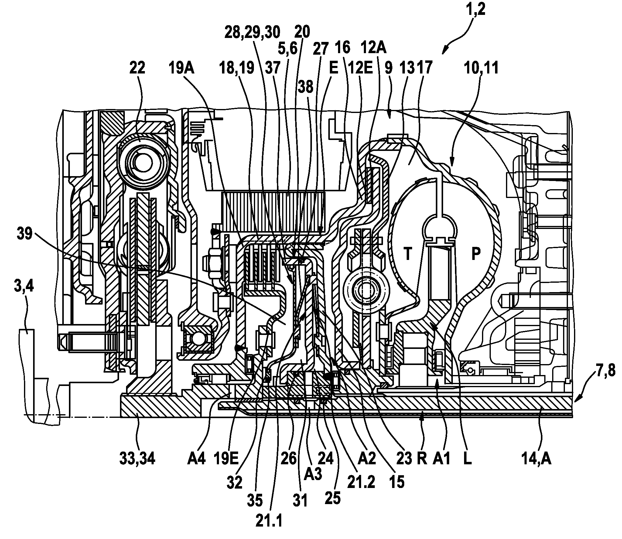
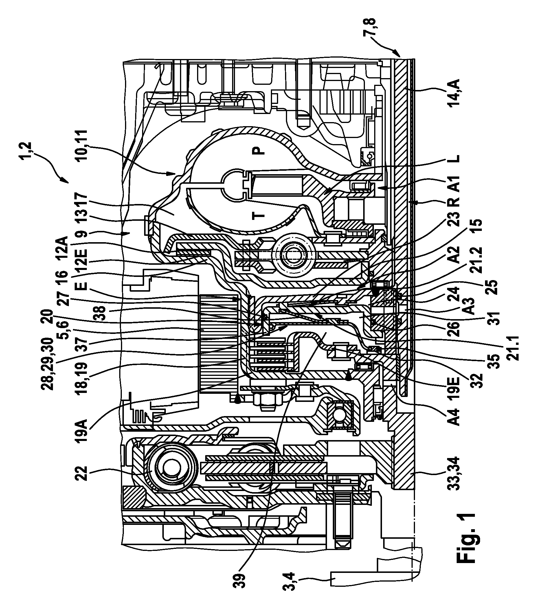
Power transmission and drive unit according to the invention, is for application in drive trains in hybrid systems with at least two prime movers, which can be coupled with a
consumer via a power transmission unit, in particular transmission. Between a first prime mover and the power transmission unit a device for connecting / disconnecting the power flow between the latter and the power transmission unit is provided, comprising a friction clutch with a first clutch part and a second clutch part, which can be actuated with pressure medium, and can be brought in active connection with a piston element that can be pressurized with pressure medium, wherein, the means are provided for controlling the rotary velocity difference, by means of flow medium on both face sides of the piston element.
[0008]The solution according to the invention enables effective shielding of the piston element of the
servo-unit, allocated to the selectable clutch, from axial forces resulting from the hydrodynamic effects, in particular, by reduction or compensation of the
axial force resulting through this and the displacement of the piston element support on a different connection element, with elements simply executed in the selectable clutch device, in particular, elements that can be integrated in a wet clutch, free of additional modification for individual subassemblies and control of clutch actuation.
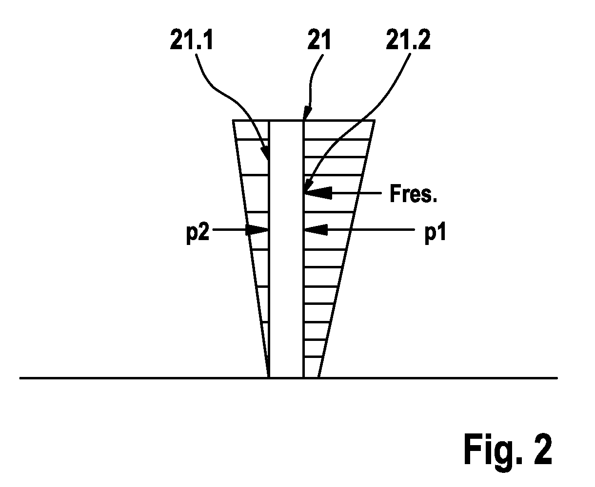
[0009]The means for controlling the rotary velocity difference of the flow medium on both sides of the piston element, in the simplest case, comprise an influence element rotatable at synchronous rotation speed with the piston element of the servo unit and in the radial direction it is located away from the piston element of the shifting device of the selectable clutch by forming a further second pressure chamber towards the piston element. The controlling element can have different embodiments. It is decisive that through the flow medium present in the interstice formed between the controlling element and the piston element, a dragging effect is generated, which spends the rotational speed of the flow medium on the piston's rotational speed.
[0010]The controlling element can be formed, in accordance with one embodiment, as a disc-shaped or ring disc-shaped element, or it is formed in the form of a piston element that features a fully closed surface in the circumferential direction. To ensure that the rotational speed is synchronous, the controlling element is non-rotatably connected with the piston element of the servo unit of the selectable clutch device or the respective element is connected non-rotatably with respect to the latter, for example, movably in the axial direction and is supported on a connection element in axial direction. Through the support on a connection element formed by an arbitrary component of the selectable clutch device, with exception of the piston element of the servo unit, the piston element of the servo unit can be kept free from bearing the axial forces. The controlling element is non-rotatably connected and supported in one embodiment with a hub connected with the piston element of the servo unit of the selectable clutch device.

