System for optical recognition of the position and movement of an object on a positioning device

a positioning device and optical recognition technology, applied in the field of optical recognition of the position and/or movement of an object on a positioning device, can solve the problems of inability to use recognition systems, inability to accurately determine the position or orientation of objects, and inability to use optical recognition systems

Inactive Publication Date: 2012-12-18
THE SWATCH GRP RES & DEVELONMENT LTD
View PDF21 Cites 6 Cited by
  • Summary
  • Abstract
  • Description
  • Claims
  • Application Information

AI Technical Summary

Benefits of technology

[0006]It is thus an object of the invention to provide a system that optically recognises the position and/or movement of an object on a positioning devi

Problems solved by technology

One drawback of these optical recognition systems essentially lies in the fact that the position or orientation of the object, determined by its outline, is not precise.
Moreover, these recognition systems cannot be used if the object is spherical in shape, since the determination of the outline of the object is identical in any position or orientation.
These optical recognition systems therefore cannot be used, for

Method used


Image

  • System for optical recognition of the position and movement of an object on a positioning device
  • System for optical recognition of the position and movement of an object on a positioning device
  • System for optical recognition of the position and movement of an object on a positioning device

Examples


Embodiment Construction

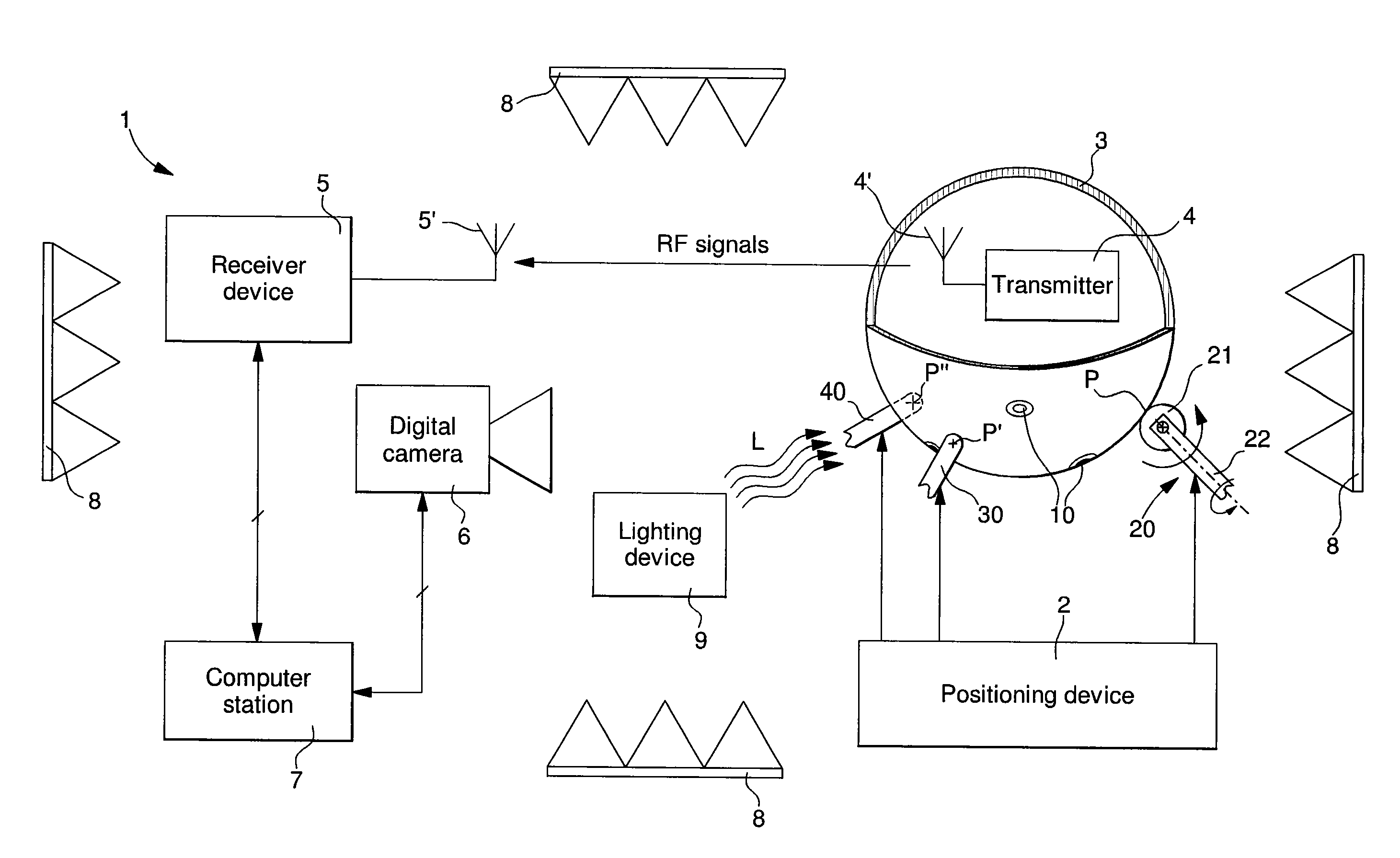
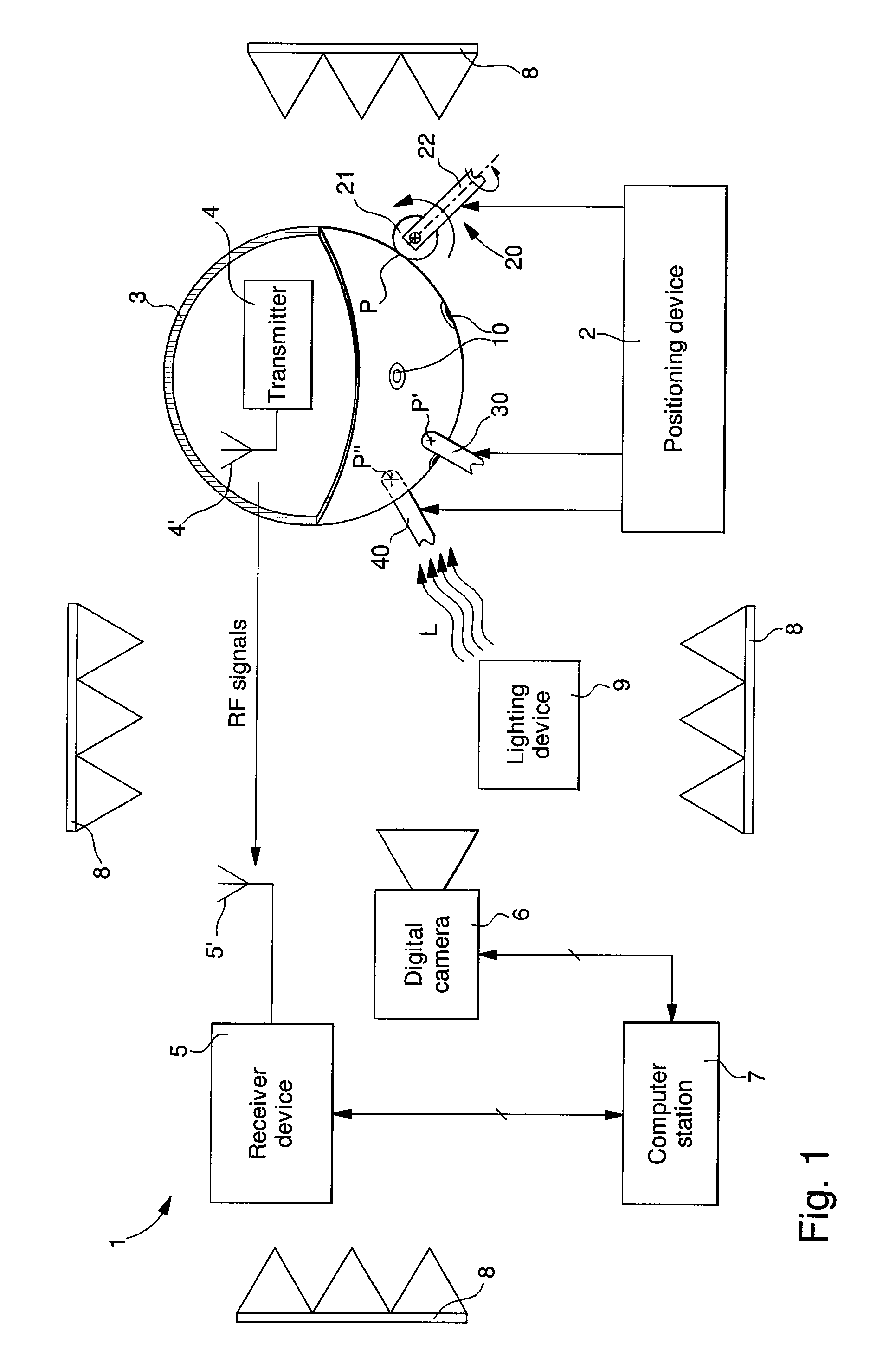
[0024]In the following description, all of the elements of the system for optical recognition of the position and / or movement of an object on a positioning device, which are well known to those skilled in this technical field, will only be explained in a simplified manner. It should be noted that the optical recognition system could be used without limitations in various applications in which the precise position of an object, placed on a support or positioning device, has to be known. The object may also be a receiving antenna for picking up radio frequency signals, which must be precisely oriented on the positioning device. The object may also be a projector, a loudspeaker, an indicator, or any other electronic object or instrument. However, in the following description, reference will be made only to an optical recognition system that forms part of a radiation measuring system for the transmitting antenna of an electronic device.

[0025]FIG. 1 illustrates schematically all of the e...


PUM


Abstract

The optical recognition system determines the position and/or movement of an object (3) on a positioning device (2). The positioning device includes means (20, 21, 22) for driving the object in rotation and/or along a curvilinear or rectilinear path. The optical recognition system includes optical detection means, such as a digital camera (6), for detecting the position or orientation of the object, and a data processing station (7) for data supplied by the detection means. A certain number of different figures or references are distributed over the external surface of the object. The arrangement of each figure on the external surface of the object enables the detection means, associated with the data processing station, to determine the position or orientation of the object on the positioning device. The figures are formed by circular barcodes (10), wherein each circular barcode defines a precise position of the object (3) on the positioning device.

Description

[0001]This is a National Phase Application in the United States of America. International Patent Application No. PCT / EP2007 / 055609 filed Jun. 6, 2007, which claims priority of European Patent Application No. 06115988.5, filed Jun. 23, 2006. The entire disclosures of the above patent applications are hereby incorporated by reference.FIELD OF THE INVENTION[0002]The invention concerns a system for the optical recognition of the position and / or movement of an object on a positioning device. The positioning device includes means for driving the object in rotation and / or along a curvilinear or rectilinear path. The system further includes means for optically detecting the position or orientation of the object, and a data processing station for data supplied by the detection means.BACKGROUND OF THE INVENTION[0003]For recognising the position and / or orientation of an object, some optical recognition systems can determine mainly the outline of the object on its support, for example on a posi...

Claims


Application Information

Patent Timeline
IPC IPC(8): G06K9/00
CPCG01S5/163G01R29/10G01S17/74
Inventor GRANGE, MATTHIEUCASAGRANDE, ARNAUD
Owner THE SWATCH GRP RES & DEVELONMENT LTD
Why Eureka
Try Eureka