Refrigerating device

Inactive Publication Date: 2013-07-23
AHT COOLING SYSTEMS GMBH
View PDF24 Cites 1 Cited by
  • Summary
  • Abstract
  • Description
  • Claims
  • Application Information

AI Technical Summary

Benefits of technology

[0005]It is therefore the object of the present invention to design a refrigerating device for deep-frozen products of the type described at the beginning having a simple design in such a way that a maintenance outlay caused by icing may be kept low.
[0007]If the product chamber has a drainage channel for the condensed water on at least the side wall impinged by the evaporator, not only may the condensed water be removed easily by the channel upon deicing of the refrigerating chamber, but rather, if the evaporator impinges the temperature of the product chamber via this side wall of the product chamber, the drainage channel is at least partially also heated, which ensures safe removal of the condensed water, although a comparatively low temperature of the deep-frozen products acts on the drainage channel. Therefore, the deep-frozen products may remain in the product chamber during deicing, so that the refrigerating device for deep-frozen products according to the present invention is particularly distinguished by its ease of operation and by the comparatively low maintenance outlay in regard to an ice-free product chamber. It is unimportant whether the drainage channel is provided as a separate component in the product chamber, or is shaped in the side wall of the refrigerating device. In addition, a uniform temperature distribution may be achieved in the product chamber if the evaporator impinges the temperature of the product chamber via the side wall of the product chamber.
[0010]If the drainage channel is implemented by the side wall and by a profiled part fastened to the side wall, advantageous removal conditions result for the condensed water, because the heated side wall also makes the removal of the condensed water easier as a part of the channel. In addition, no material transition has to be overcome by the draining condensed water so that it may then be received by the drainage channel, so that droplet formations at the inlet of the drainage channel, which in turn result in visible icing, may be avoided.
[0012]A spacer, for example, in the form of a lattice insert, may be provided in the product chamber for spacing apart the refrigerated products from both the side wall impinged by the evaporator and also from the drainage channel. Therefore, impingement of the products with condensed water and also heating of the deep-frozen products because they press against the side wall may be prevented upon deicing of the product chamber.

Problems solved by technology

It is unimportant whether the drainage channel is provided as a separate component in the product chamber, or is shaped in the side wall of the refrigerating device.

Method used


Image

  • Refrigerating device
  • Refrigerating device
  • Refrigerating device

Examples


Embodiment Construction

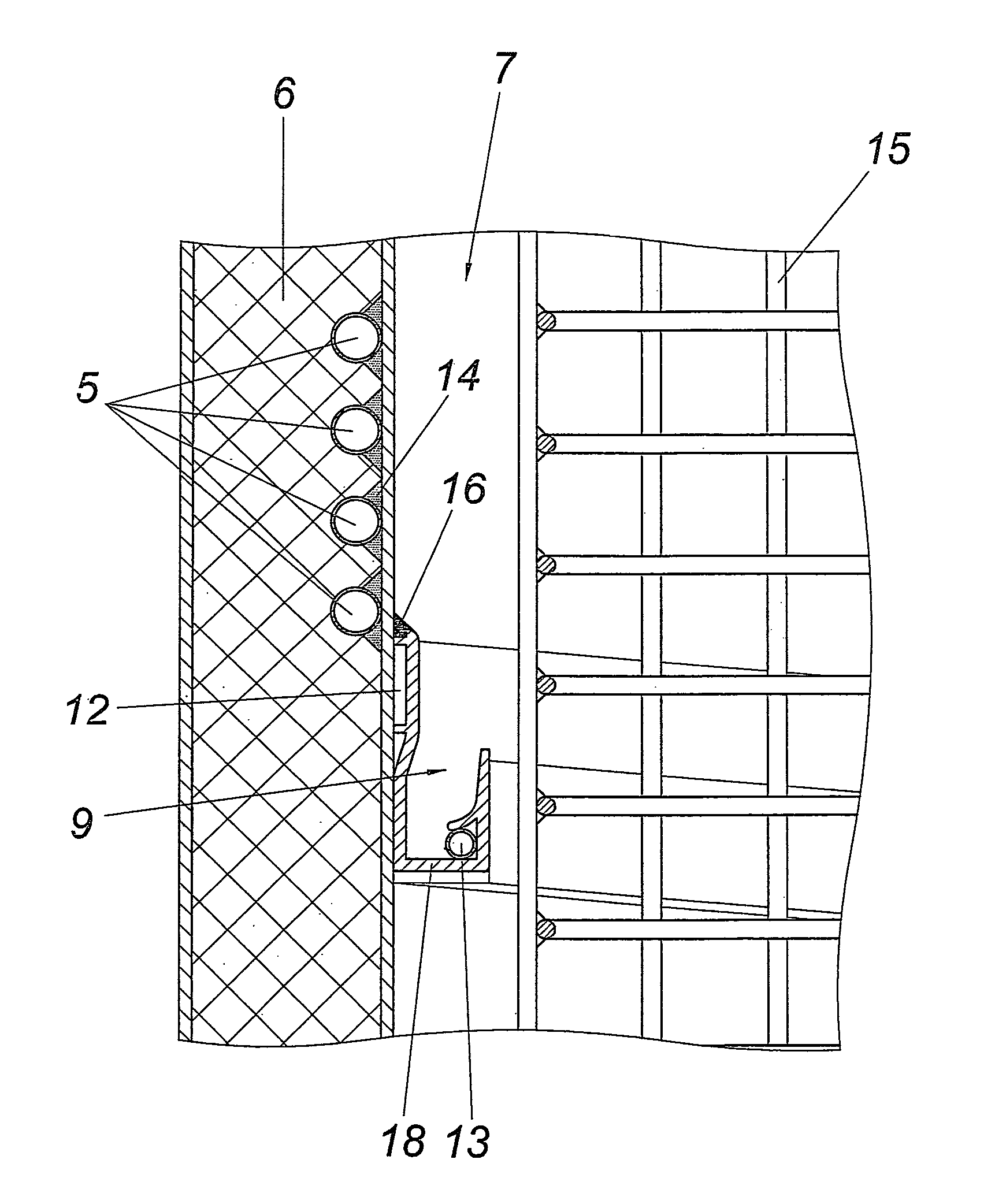
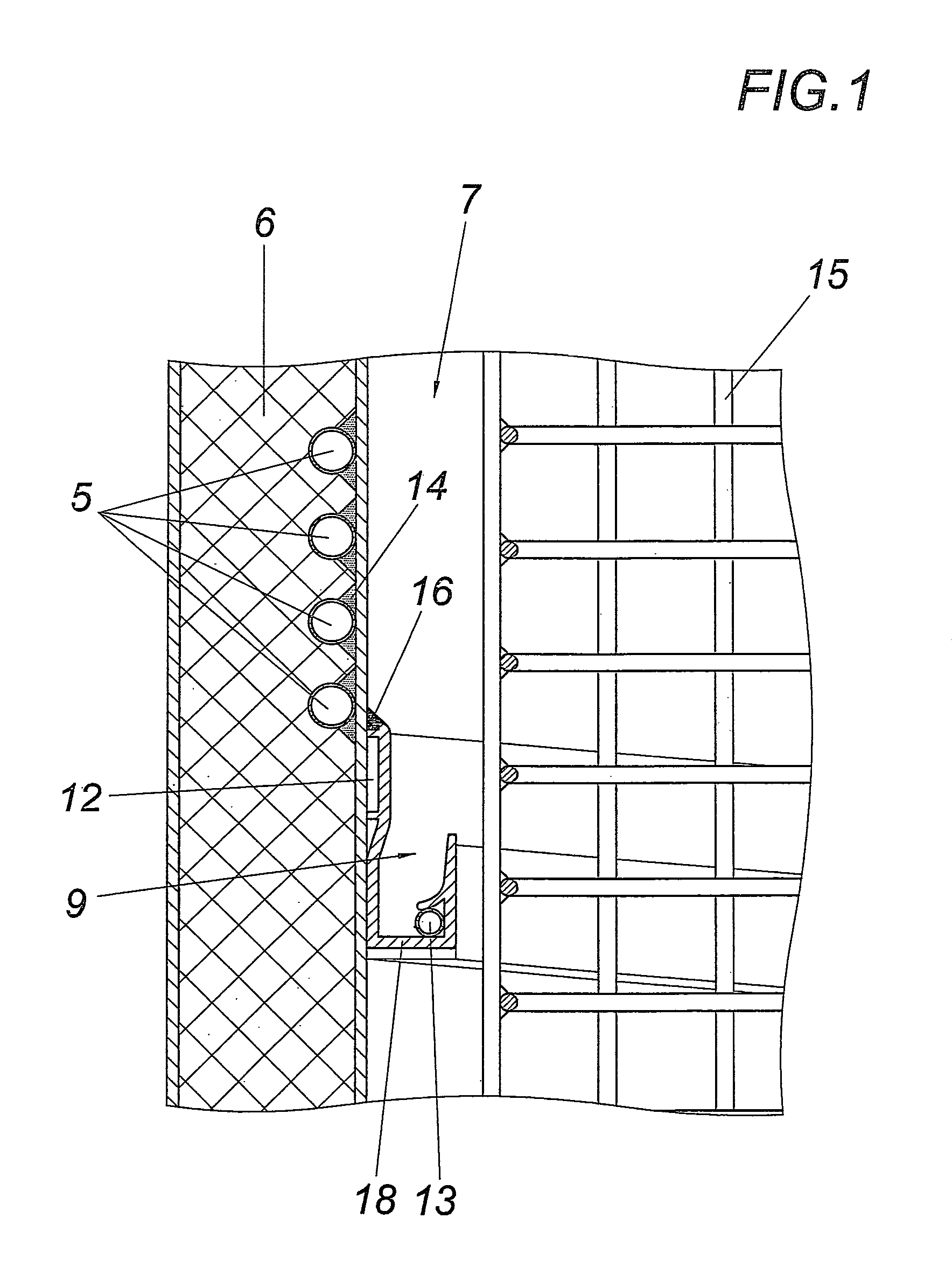
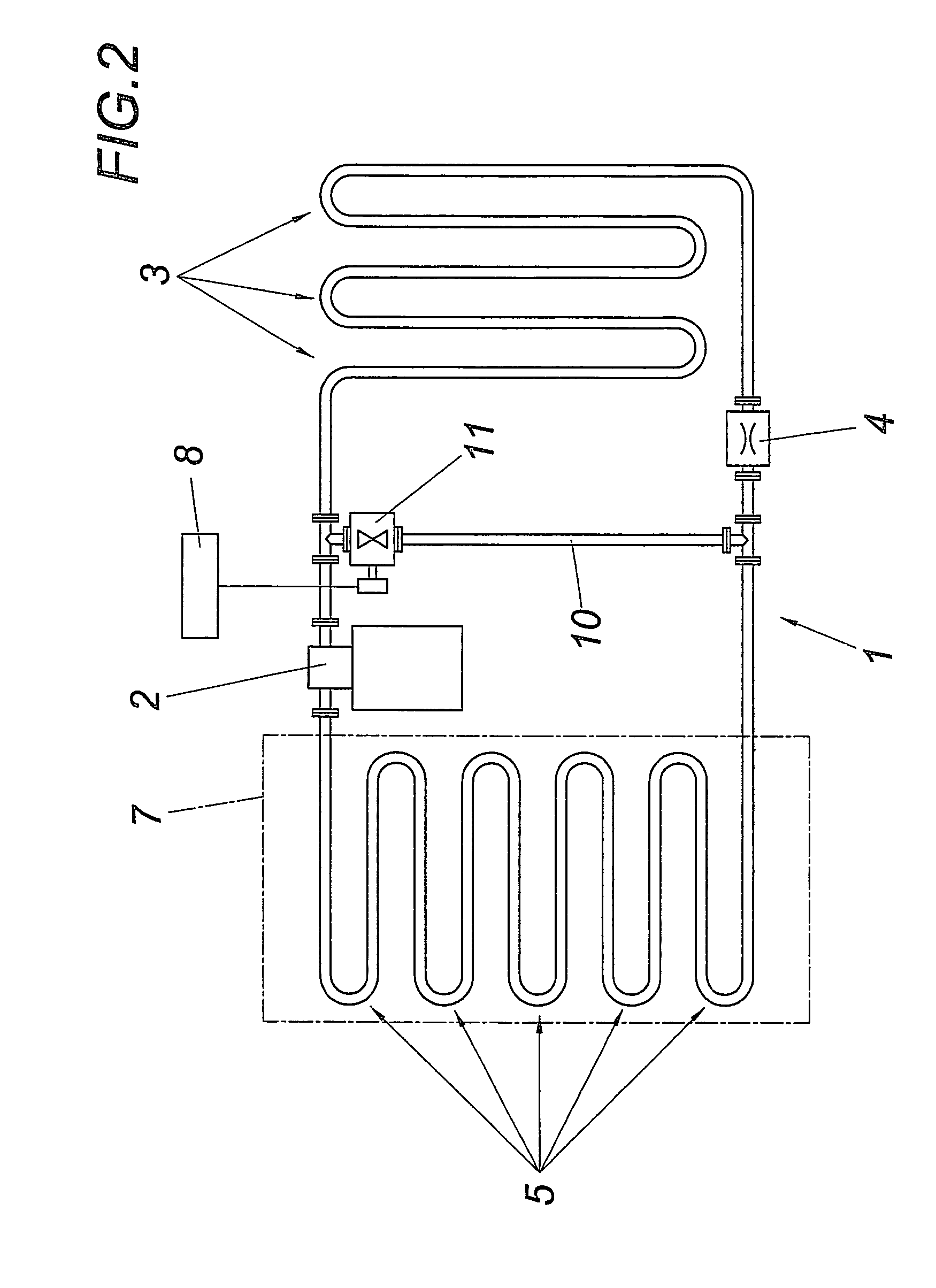
[0017]The refrigerating device for deep-frozen products illustrated as an example has a coolant loop 1 comprising a compressor 2, a condenser 3, a throttle 4, and an evaporator 5 (FIG. 2). The evaporator 5 impinges a side wall 6 of the product chamber 7 (FIG. 1), in which products (not shown in greater detail) are deep-frozen. A control unit 8 is provided for deicing the product chamber 7, and a drainage channel 9, 17 for the condensed water is provided in the product chamber 7 on the side wall 6 impinged by the evaporator, the control unit 8 at least partially heating the drainage channel 9, 17 via the side wall 6 impinged by the evaporator upon deicing of the product chamber 7. Therefore, it may be ensured that condensed water running off of the side wall 6 flows into the drainage channel 9, 17, without having to fear freezing of the condensed water because of the cold of the deep-frozen products.

[0018]The side wall 6 may be heated using a simple design with the aid of the evapora...


PUM


Abstract

A refrigerating device for deep-frozen products has a coolant loop including a compressor, a condenser, a throttle, and an evaporator. The device also has a product chamber temperature-impinged by the evaporator, and a control unit provided for deicing, which works together with the coolant loop in such a way that upon deicing, both the evaporator and also a drainage channel provided for receiving the condensed water are heated. The evaporator impinges the temperature of the product chamber via the side wall of the product chamber, and at least the side wall impinged by the evaporator has the drainage channel, the evaporator at least partially heating the drainage channel upon deicing of the product chamber.

Description

CROSS REFERENCE TO RELATED APPLICATIONS[0001]Applicant claims priority under 35 U.S.C. §119 of Austrian Application No. A 966 / 2005 filed Jun. 8, 2005. Applicant also claims priority under 35 U.S.C. §365 of PCT / AT2006 / 000045 filed Feb. 6, 2006. The international application under PCT article 21(2) was not published in English.FIELD OF THE INVENTION[0002]The present invention relates to a refrigerating device for deep-frozen products having a coolant loop comprising a compressor, a condenser, a throttle, and an evaporator, having a product chamber temperature-impinged by the evaporator, and having a control unit provided for deicing, which works together with the coolant loop in such a way that both the evaporator and also a drainage channel provided for receiving the condensed water are heated upon deicing.DESCRIPTION OF THE PRIOR ART[0003]Deep-freezing devices, such as freezer chests, are known from the prior art, which deep-freeze products in a product chamber via an evaporator of ...

Claims


Application Information

Patent Timeline
Patent Type & Authority Patents(United States)
IPC IPC(8): F25D21/14F25D23/00
CPCF25B47/022F25B2339/023F25B2400/0403F25B2400/0411F25D21/14F25D23/061F25D23/066F25D2321/1441
Inventor RESCH, REINHOLD
Owner AHT COOLING SYSTEMS GMBH
Why Eureka
Try Eureka